
Radar-based guidance and wireless control for automated vehicle platooning and lane keeping on an automated highway system

a technology of automated highways and wireless control, applied in process and machine control, navigation instruments, instruments, etc., can solve the problems of not providing the necessary reliability and functional safety assurance of an automated highway, current solutions may fail to provide reliable lateral and longitudinal guidance with heterogeneous vehicles for forming dynamic platoons, and computer vision-based systems can suffer in bad weather conditions and not provide reliable guidan

Inactive Publication Date: 2019-08-08
SATYAVOLU SURYA
View PDF7 Cites 6 Cited by
  • Summary
  • Abstract
  • Description
  • Claims
  • Application Information

AI Technical Summary

Benefits of technology

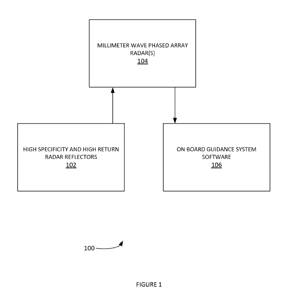
The patent is about a computerized system for automatic guidance of a vehicle using radar sensors. The system includes a front-looking radar sensor pair placed at the front of the vehicle, side-looking radar sensors placed on the sides of the vehicle, and a path-planning module that determines the vehicle's position in the roadway and provides a path for the vehicle. The vehicle follows the path planned by the system using a trajectory-tracking module. The system also includes a vehicle-dynamics controller that manages the vehicle's dynamics to implement the planned path. The system can also include a set of radar reflectors placed perpendicular to a line of sight, which provide a guided pathway for the vehicle.

Problems solved by technology

These systems cannot provide the necessary reliability and functional safety assurance for an automated highway.
For example, in a platooning content, the current solutions may fail to provide the reliable lateral and longitudinal guidance with heterogeneous vehicles for forming dynamic platoons.
It is further noted that computer vision-based systems can suffer in bad weather conditions and not provide reliable guidance with lane keeping and platooning situations.

Method used


Image

  • Radar-based guidance and wireless control for automated vehicle platooning and lane keeping on an automated highway system
  • Radar-based guidance and wireless control for automated vehicle platooning and lane keeping on an automated highway system
  • Radar-based guidance and wireless control for automated vehicle platooning and lane keeping on an automated highway system

Examples


example definitions

[0025]Model predictive control (MPC) is an advanced method of process control. Model predictive controllers can use dynamic models of process, (e.g. linear empirical models obtained by system identification, etc.). An MPC can enable the current timeslot to be optimized, while keeping future timeslots in account. This can be achieved by optimizing a finite time-horizon, and / or implementing the current timeslot and then optimizing again.

[0026]Path can be a road, highway, rail system, runway, boat route, bike path, etc., according to various embodiments.

[0027]Phased array can be an array of antennas in which the relative phases of the respective signals feeding the antennas are set in such a way that the effective radiation pattern of the array is reinforced in a desired direction and suppressed in undesired directions.

[0028]Platooning can be a method of grouping vehicles into platoons as a way of increasing the capacity of roads. Vehicle platoons can decrease the distances between veh...


PUM


Abstract

A computerized system onboard a vehicle for automatic radar-based vehicle guidance includes a front-looking radar sensing module. The front-looking radar sensing module comprises a pair of radar sensors. The pair of radar sensors are placed at front of vehicle. The pair of radar sensors emits radar waves at a specified radar frequency and senses reflected radar waves. The radar waves are reflected by a set of radar reflectors placed at the side of a roadway at a distance ahead of the vehicle on the roadway. The front-looking radar sensing module obtains a reflected-radar information from the pair of radar sensors and determines the distance between the vehicle and the radar reflectors ahead of the vehicle at a specified time.

Description

CROSS-REFERENCE TO RELATED APPLICATIONS[0001]This application is a claims priority to U.S. patent application Ser. No. 15 / 197,750, titled Radar-Based Guidance and Wireless Control For Automated Vehicle Platooning And Lane Keeping On An Automated Highway System and filed on Jun. 29, 2016. U.S. patent application Ser. No. 15 / 197,750 claims priority to U.S. provisional patent application No. 62 / 187,418, titled Radar Based Guidance and Wireless Control for Platooning and Lane Keeping on an Automated Highway System and filed on Jul. 1, 2015. These applications are hereby incorporated by reference in their entirety.BACKGROUND[0002]The current lane keeping systems make use of vision based camera systems with painted lane separation markers. These systems cannot provide the necessary reliability and functional safety assurance for an automated highway. For example, in a platooning content, the current solutions may fail to provide the reliable lateral and longitudinal guidance with heteroge...

Claims


Application Information

Patent Timeline
Patent Type & Authority Applications(United States)
IPC IPC(8): G05D1/02G05D1/00G01C21/34G01S13/93H01Q15/18G01S13/931
CPCG05D1/0257G05D1/0088G05D1/0223G05D1/0293G01C21/3438G01S13/931H01Q15/18G05D2201/0213G01S2013/9375G01S2013/9385G01S2013/0245G01S2013/9339G01S2013/9329G01S2013/93274G01S2013/93271
Inventor SATYAVOLU, SURYA
Owner SATYAVOLU SURYA
Learn More