Modular adjustable corpectomy cage

a module-based, adjustable technology, applied in the field of interbody spinal implants, can solve the problems of lack of proper biomechanical support, deformation, deformation of the vertebrae and discs, loss of structural integrity,

Active Publication Date: 2019-08-15
TITAN SPINE
View PDF0 Cites 1 Cited by
  • Summary
  • Abstract
  • Description
  • Claims
  • Application Information

AI Technical Summary

Benefits of technology

[0020]The tool has an expander and an inserter. The tool engages a tool holding feature on the modular cage and positions the modular cage at a surgical site within the patient. The expander slides the body along the at least one leg to separate the body from the column continuously in situ and thereby define the height of the implant. The inserter positions the shim between the

Problems solved by technology

Over time, the vertebrae and discs may become diseased or infected, develop deformities such as tears and cracks, or simply lose structural integrity, for example bulge or flatten.
These impaired vertebrae and discs can result in a lack of proper biomechanical support, and are often associated with chronic back pain.
This location is not the preferable seating position for an implant system, however, because only a relatively small portion of the vertebral endplate is contacted by these cylindrical implants.
The seating of these threaded cylindrical implants may also compromise biomechanical integrity by reducing the area in which to distribute mechanical forces, thus increasing the apparent stress experienced by both the implant and vertebrae.
Still further, a substantial risk of implant subsidence (defined as sinking or settling) into the softer cancellous bone of the vertebral body may arise from such improper seating.
Such allograft bone material restricts the usable size and shape of the resultant implant.
Therefore, these cages may not be of a sufficient size to contact the strong cortical bone, or apophyseal rim, of the vertebral endplate.
These size-limited implant systems may also poorly accommodate related instrumentation such as drivers, reamers, distractors, and the like.
For example, these implant systems may lack sufficient structural integrity to withstand repeated impact and may fracture during implantation.
Still further, other traditional non-allograft ring-shaped cage systems may be size-limited due to varied and complex supplemental implant instrumentation which may obstruct the disc space while requiring greater exposure of the operating

Method used


Image

  • Modular adjustable corpectomy cage
  • Modular adjustable corpectomy cage
  • Modular adjustable corpectomy cage

Examples


Embodiment Construction

[0058]Various terms relating to aspects of the present disclosure are used throughout the specification and claims. Such terms are to be given their ordinary meaning in the art unless otherwise indicated. Other specifically defined terms are to be construed in a manner consistent with the definition provided in this document.

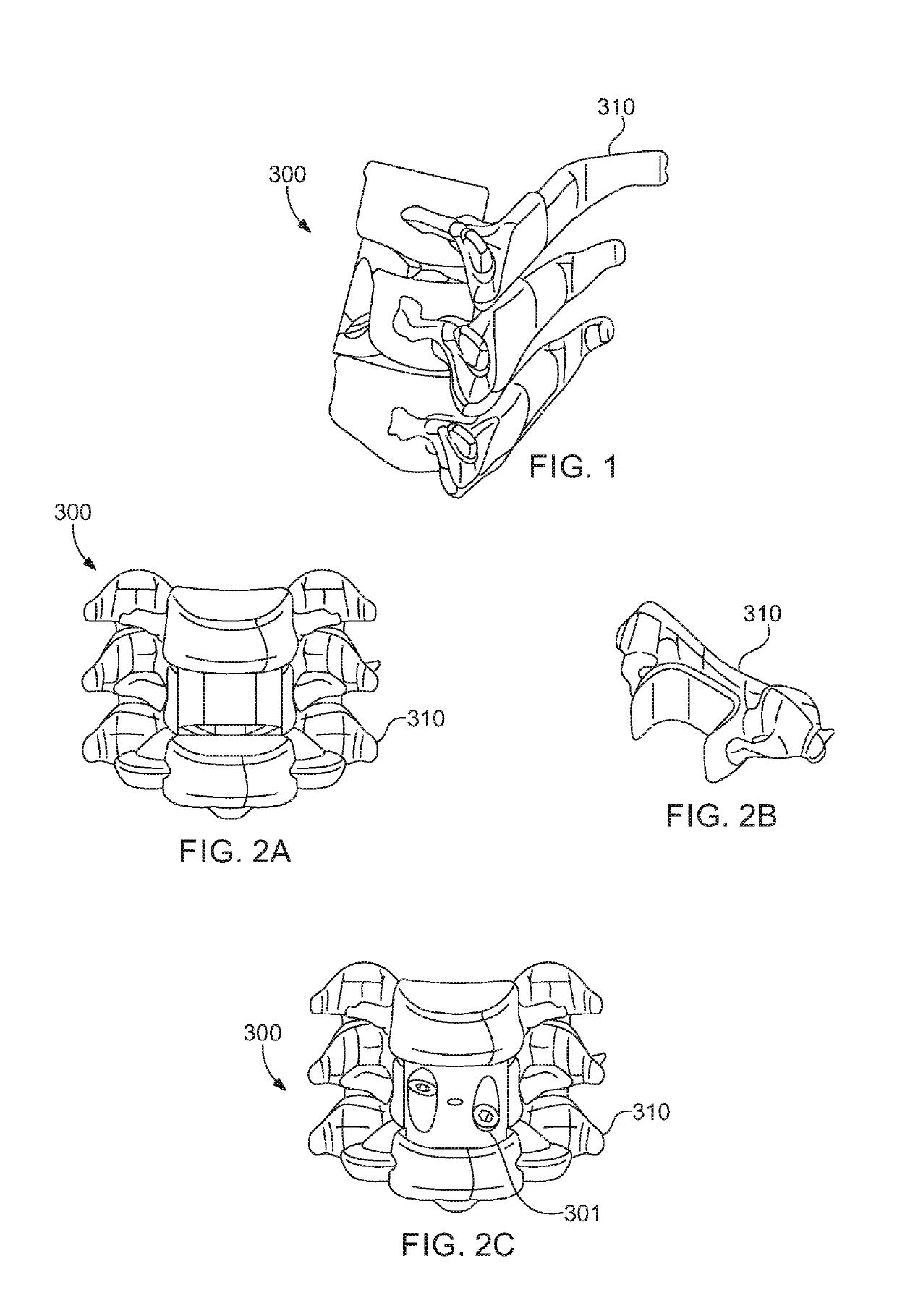
[0059]As used throughout, the singular forms “a,”“an,” and “the” include plural referents unless expressly stated otherwise. A “patient” may be any animal, including mammals such as companion animals, laboratory animals, and non-human primates. Human beings are preferred. A functional spinal unit includes a vertebrae and the intervertebral discs between a superior and inferior vertebrae. A functional spinal unit may include a cervical functional spinal unit, a thoracic functional spinal unit, or a lumbar functional spinal unit.

[0060]Referring now to the drawing, in which like reference numbers refer to like elements throughout the various figures that comprise t...


PUM


Abstract

A system for use during surgical procedures. The system includes an implant and a tool. The implant combines a modular adjustable cage and a shim that locks the cage into position, after the cage has been adjusted to its final position and at its final height, in situ. The tool combines an expander and an inserter. A related method of using the system is also provided.

Description

FIELD OF THE INVENTION[0001]The invention relates generally to interbody spinal implants and methods of using such implants and, in particular, to a modular adjustable corpectomy cage.BACKGROUND OF THE INVENTION[0002]In the simplest terms, the spine is a column made of vertebrae and discs. The vertebrae provide the support and structure of the spine while the spinal discs, located between the vertebrae, act as cushions or “shock absorbers.” These discs also contribute to the flexibility and motion of the spinal column. Over time, the vertebrae and discs may become diseased or infected, develop deformities such as tears and cracks, or simply lose structural integrity, for example bulge or flatten. These impaired vertebrae and discs can result in a lack of proper biomechanical support, and are often associated with chronic back pain.[0003]Several surgical techniques have been developed to address spinal defects, such as vertebral or disc degeneration, deformity, or both. Spinal fusion...

Claims


Application Information

Patent Timeline
IPC IPC(8): A61F2/44A61F2/46
CPCA61F2/4465A61F2/4611A61F2/442A61F2002/30601A61F2002/30383A61F2002/30556A61B2017/0256A61F2/4455A61F2/447A61F2/4637A61F2002/30224A61F2002/30235A61F2002/30261A61F2002/30481A61F2002/30487A61F2002/30537A61F2002/3055A61F2002/30604A61F2002/30772A61F2002/30828A61F2002/4622A61F2002/4628A61F2220/0025A61F2002/30593A61F2/4603
Inventor ULRICH, JR., PETER F.KENNEDY, ERICTURNER, CHARLES J.
Owner TITAN SPINE
Why Eureka
Try Eureka