Method for joining dissimilar metal plates

a metal plate and dissimilar technology, applied in the field of joining can solve the problems of insufficient joint strength of dissimilar metal plates, insufficient current supply of other metal plates, and difficulty in generating heat with current, so as to achieve the effect of enhancing joint strength and enhancing joint strength of two dissimilar metal plates made of different metallic materials

Active Publication Date: 2019-08-15
TOYOTA JIDOSHA KK
View PDF0 Cites 1 Cited by
  • Summary
  • Abstract
  • Description
  • Claims
  • Application Information

AI Technical Summary

Benefits of technology

[0016]In addition, a steel plate having a plating film formed thereon, such as a galvanized steel plate, is difficult to be joined with a sufficient joint strength to an aluminum plate or an aluminum alloy plate. However, in such a configuration, since metal of the plating film formed on the surface of the steel plate diffuses to the melted aluminum or aluminum alloy, and a fresh surface of the steel plate is thus generated, joint strength can be enhanced.
[0017]According to the present disclosure, the joint strength of two dissimilar metal plates made of different metallic materials can be enhanced.

Problems solved by technology

However, when dissimilar metal plates like an aluminum alloy plate and a steel plate are joined using the joining method disclosed in JP 2012-152786 A, one of the metal plates with lower volume resistivity than that of the other metal plate is more difficult to generate heat with the current supplied thereto, in comparison with the other metal plate.
Thus, it follows that the other metal plate is supplied with an excessive amount of current.
Consequently, it is concerned that voids and the like may be generated in a portion of the other metal plate that has been supplied with the excessive amount of current and thus has melted due to the current, and thus that a sufficient joint strength of the dissimilar metal plates may not be obtained.
Therefore, voids resulting from excessive heating are unlikely to be formed in the second metal plate or in the joined portion thereof.
Further, if the joined portion that has been heated due to excessive heating is cooled naturally, the structure of the joined portion is likely to become coarse.
In addition, a steel plate having a plating film formed thereon, such as a galvanized steel plate, is difficult to be joined with a sufficient joint strength to an aluminum plate or an aluminum alloy plate.

Method used


Image

  • Method for joining dissimilar metal plates
  • Method for joining dissimilar metal plates
  • Method for joining dissimilar metal plates

Examples


example 1-1

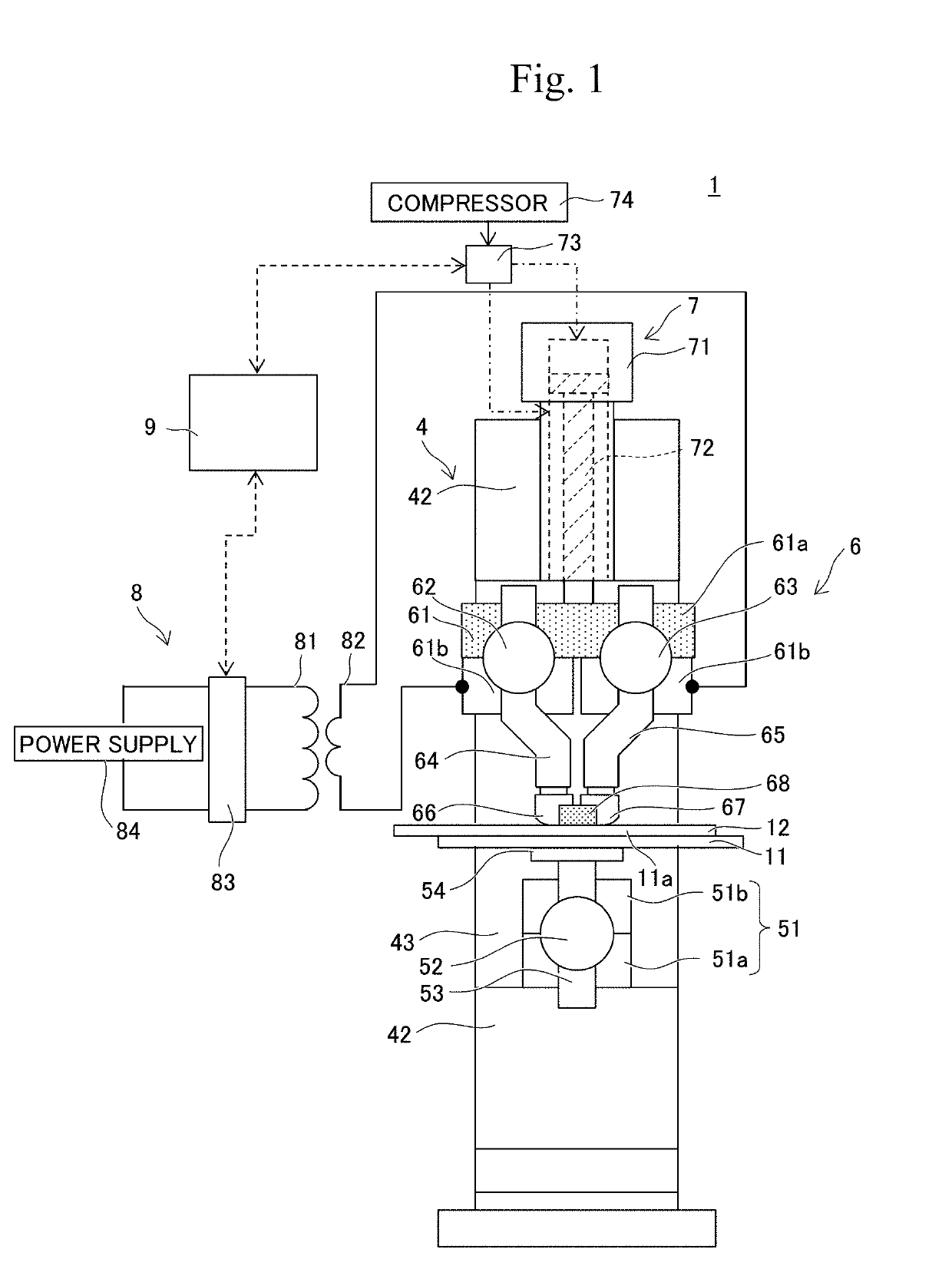
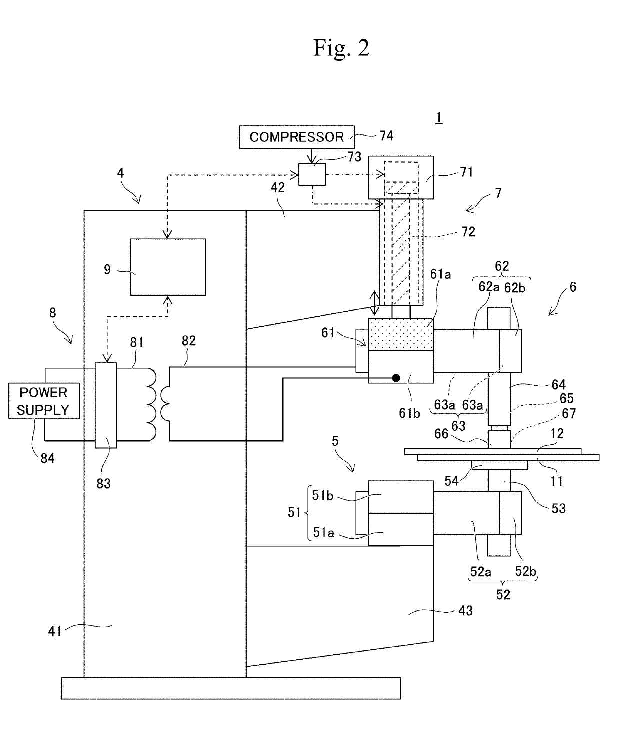
[0065]The first metal plate and the second metal plate were joined using the resistance-welding apparatus shown in FIG. 1. First, 6000 series aluminum alloy with a plate thickness of 1.0 mm was prepared as the first metal plate, and a high-tension galvanized steel plate with a plate thickness of 0.7 mm was prepared as the second metal plate. Next, the first metal plate and the second metal plate were overlaid one on top of the other, and a pair of electrodes were brought into contact with the second metal plate with a pressure applied by the pair of electrodes and the pressurizing member set to 3.5 kN, a current supply time set to 0.42 msec, and welding current set to 8.4 kA as shown in Table 1, so that a test piece having the first metal plate and the second metal plate that are joined was produced.

examples 1-2 to 1-8

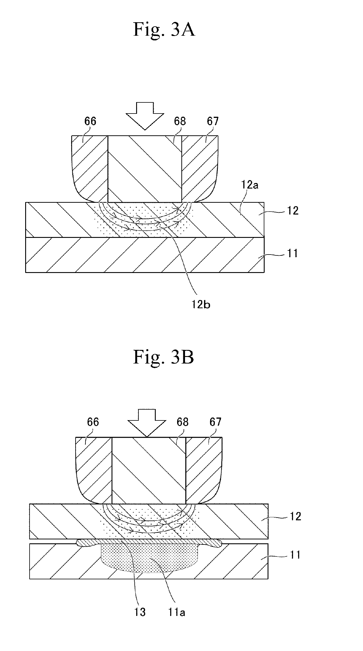
[0066]As in Example 1-1, test pieces of Examples 1-2 to 1-8 were produced. These examples are different from Example 1-1 in the conditions of the value of current supplied during welding as shown in Table 1 and FIG. 4. In Example 1-8, the second metal plate generated excessive heat during welding, and thus, the first metal plate was heated excessively, and the thus melted first metal scattered from the portion between the first metal plate and the second metal plate. In Examples 1-1 to 1-7, the first metal melted during welding did not scatter. Table 1 show these results. In Table 1, the presence or absence of the melting of the second metal plate during welding indicates the result obtained by confirming whether or not the second metal plate was welded to the electrodes and by observing the structure as described below.

examples 2-1 to 2-6

[0068]As in Example 1-1, test pieces of Examples 2-1 to 2-6 were produced. These examples are different from Example 1-1 in the conditions of the value of current supplied and the current supply time during welding as shown in Table 1 and FIG. 4. The current supply time of each of Examples 2-1 to 2-6 was 0.50 msec. In Example 2-6, the first metal of the first metal plate was heated excessively during welding, and the thus melted first metal scattered from the portion between the first metal plate and the second metal plate as in Example 1-8. Meanwhile, in Examples 2-1 to 2-5, the first metal melted during welding did not scatter. Table 1 shows the results.


PUM

PropertyMeasurementUnit
melting pointaaaaaaaaaa
thicknessaaaaaaaaaa

Abstract

A method for joining two dissimilar metal plates having different volume resistivity with enhanced joint strength. The method includes overlaying a first metal plate made of first metal and a second metal plate made of second metal with higher volume resistivity and higher melting point in comparison with the first metal, bringing a pair of electrodes into contact with the surface of a portion of the second metal plate overlapping the first metal plate, supplying current between the electrodes so as to resistance-heat the second metal present in a current-flowing region to a temperature lower than the melting point of the second metal and higher than the melting point of the first metal, thereby partially melting the first metal plate with the heat so that an intermetallic compound is generated between the first and second metal plates, and thus joining the first and second metal plates via the intermetallic compound.

Description

CROSS REFERENCE TO RELATED APPLICATIONS[0001]The present application claims priority from Japanese patent application JP 2018-021780 filed on Feb. 9, 2018, the content of which is hereby incorporated by reference into this application.BACKGROUNDTechnical Field[0002]The present disclosure relates to a method for joining two dissimilar metal plates that are different in volume resistivity.Background Art[0003]Conventionally, spot welding has been performed to join an aluminum alloy plate and a steel plate. As the spot welding of this type, for example, JP 2012-152786 A proposes a method for joining dissimilar metal plates that includes overlaying an aluminum alloy plate and a steel plate one on top of the other, sandwiching the overlapping portion thereof between a pair of electrodes and pressurizing them, and supplying current between the electrodes while maintaining the pressurized state so as perform resistance spot welding. According to such a joining method, when current is suppli...

Claims


Application Information

Patent Timeline
Patent Type & Authority Applications(United States)
IPC IPC(8): B23K11/20B23K11/11
CPCB23K11/20B23K11/11B23K2103/04B23K2103/10B23K2103/20B23K2101/18B23K11/115B23K11/3018B23K11/315B23K11/36
Inventor TOYODA, AKIHIRO
Owner TOYOTA JIDOSHA KK
Why Eureka
Try Eureka