Transducer for High-Voltage Measuring Technology

a high-voltage measuring and transducer technology, applied in the direction of measurement instrument housing, measurement apparatus components, measurement apparatus housing, etc., can solve the problems of reducing the insulation air clearance, affecting the effect, and affecting so as to improve the functional division of components, improve the resistance to mechanical loads, and improve the effect of mechanical load resistan

Active Publication Date: 2019-08-15
KNICK ELEKTRONISCHE MESSGERATE
View PDF0 Cites 0 Cited by
  • Summary
  • Abstract
  • Description
  • Claims
  • Application Information

AI Technical Summary

Benefits of technology

[0030]Preferably, the protective hood can be secured to the housing pedestal with the inclusion of sealing elements; by way of example, in this case in specific sections said protective hood has recesses in the form of a groove, for example for receiving a sealing elastomer, which in turn together with the sealing surfaces present in specific sections of the housing guarantees a circumferential sealing. Particularly high protection against contamination and ingress of moisture is thus ensured. The protective hood can additionally serve as protection against electric shock if corresponding installation regions in which hazardous voltages and currents can occur are accessible to persons during maintenance work.
[0031]As an interim result it should be emphasized that the embodiment of the transducer according to the invention leads to a considerable space and area saving on the mounting surface by comparison with the prior art. This is achieved firstly by virtue of the upright construction with a small basic area, secondly by virtue of the arrangement of the input connections on the long sides on the central dome, and also by virtue of the protective hood that can be emplaced, as a result of which a mounting-insulation protection distance with respect to adjacent components can be kept very small. The connection space for the input connection bolts that is formed by the protective hood and the housing with its central dome can moreover be equipped with ventilation channels, such that said connection space can be ventilated in the direction toward the baseplate in order to achieve climate equalization.
[0032]In accordance with a further preferred embodiment, a respective through opening for leading an input-side high-voltage connection line through to the input connections is arranged in the housing in each case laterally alongside the dome preferably in a vertical side wall, wherein sleeves e.g. composed of an elastomer are insertable into the through openings and can act as sealing elements and anti-kink protection. Preferably, in this case, said through openings are formed in the edge of the housing pedestal facing the protective hood, as a cutout open transversely with respect to the lead-through direction of the high-voltage connection lines. Very simple mounting of the connection lines is thus achieved, which, with the protective hood removed, are pushed into said cutouts from the side if appropriate with a sleeve and then after the securing of the cable lugs on the corresponding input connection bolts with the fixing of the connection line with sleeve, the protective hood is latched onto the housing pedestal.
[0037]In order to improve the functional division of the components of the transducer, in a further preferred embodiment it can be provided that there is provided on an outer side, preferably a narrow side, of the housing, an output connection region which is separated from the transducer circuit, to which high voltage is applied, by a partition in the housing and in which the low-voltage output connections and, if appropriate, further auxiliary energy connections, operating and / or signaling elements are arranged. Thus the output connection region is fundamentally separated from the actual main region of the printed circuit board having the function-generating components of the transducer circuit, which opens up the basis for a further preferred embodiment of the invention, according to which the interior of the dome with said function-generating components can be hermetically sealed by a potting, without this potting compound penetrating into the output connection region. The potting compound that can be introduced protects the electronics against harmful environmental influences, increases the resistance to mechanical loads and ensures the electrical insulation of the various circuits on the printed circuit board relative to one another and with respect to the direct mounting environment of the transducer.
[0038]In accordance with a further embodiment of the invention, there are provided in the partition a preferably sealable slot open to the base of the housing and serving for passage of the printed circuit board, which is preferably configured in an integral fashion, and also in the printed circuit board as an extension of the slot a preferably sealable recess for passage of the partition, said recess being open to its upper edge facing away from the base. A particularly simple mountability of the printed circuit board in the housing with the partition is thus achievable, wherein the possibility of the potting of the interior is in turn maintained by means of the sealants. Specifically, as the printed circuit board is inserted into the housing during the factory assembly of the transducer, that part of the printed circuit board which mechanically and electrically connects the connection region to the remainder of the electronics descends into said slot. In this case, the slot in the partition can have sealants, e.g. an elastomer. In this case, the above-described recess in the printed circuit board is shaped such that as the printed circuit board is inserted into the housing, the partition descends into said recess of the printed circuit board. After the complete insertion of the printed circuit board, the contact locations of the printed circuit board for the contacting of the input connection bolts that are to be introduced later are then situated in the corresponding section within the central dome of the housing.
[0039]In accordance with one advantageous embodiment of the invention, it is furthermore provided that on the outer side in front of the partition a screen part is arranged in the output connection region between the section there of the printed circuit board and the low-voltage output connections fitted marginally to the printed circuit board and, if appropriate, further auxiliary connections, operating and / or signaling elements. Said screen part serves for covering the printed circuit board region located behind the output and auxiliary energy terminals and operating and signaling elements and can act as visual screen and protection against electric shock. Moreover, it can serve as inscription region and also as optical diaphragm for signaling means such as e.g. LEDs. Furthermore, the screen part can serve as guide element for test and calibration contacts or diagnosis contacts which can be used e.g. during a factory configuration or during a factory calibration.

Problems solved by technology

Particularly in the case of small signals at high potential, a high common-mode rejection (CMRR) has to be ensured since common-mode voltages can otherwise cause considerable errors.
Independently of the magnitude of the voltage to be measured, particularly in the case of large distances between signal source and signal sink, potential differences between measurement location and control technology can arise which can lead to considerable measurement errors.
As a result, in the event of negligent installation, reduced insulation air clearances can occur because the cable lugs approach one another or the opposite connection bolt or the mounting surface in an undesired manner.
As a result, there is the risk that external environment influences, such as moisture, dust, dirt, can impair the effect of the creepage paths and the metallic contact elements can be subjected to increased corrosion.
Moreover, protection against electric shock is not provided either, and so present demands in respect of safety of persons, e.g. in the context of installation and maintenance work, are not satisfied.
Particularly on the high-voltage-carrying input side of the transducer, this can lead to undesired influencings of the signal transmission and possibly of the insulation.
In addition, as a result of the spatial proximity of one of the input connection bolts to the output connection bolts situated on the side of the transducer, the creepage paths and air clearances can be disadvantageously shortened in the event of unfavorable alignment of the cable lug and / or of the connection lines and the insulation capability can thus be reduced.

Method used


Image

  • Transducer for High-Voltage Measuring Technology
  • Transducer for High-Voltage Measuring Technology
  • Transducer for High-Voltage Measuring Technology

Examples


Embodiment Construction

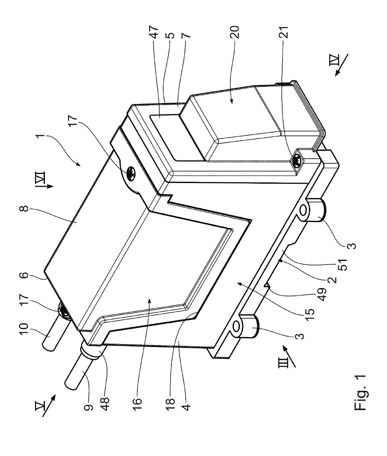
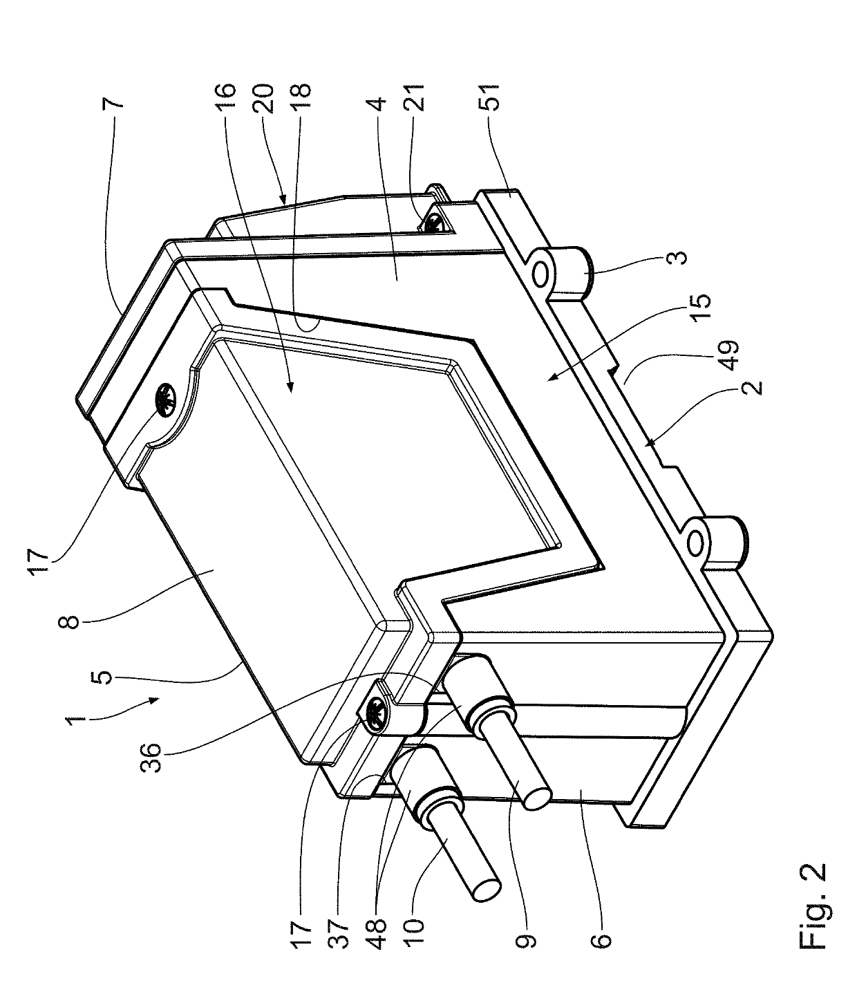
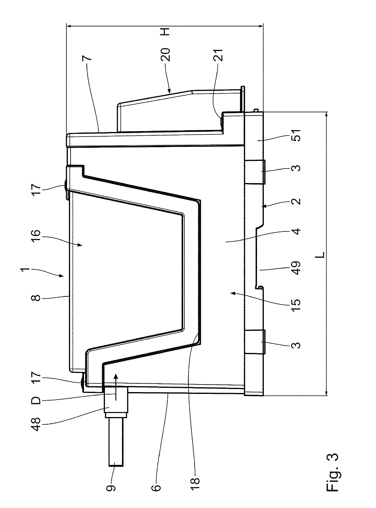
[0050]As becomes clear from FIGS. 1 to 6, the transducer for high-voltage measuring technology comprises a housing 1 composed of a customary insulating material, said housing exhibiting a parallelepipedal basic contour. In this case, an upright construction is chosen in which the base 2 of the housing 1 (without the securing eyes 3 for mounting) has a width B that is significantly smaller than the length L. In this regard, the width-length ratio of the base 2 and thus of the housing 1 is approximately 1:2.3. By contrast, the height H of the housing 1 is significantly greater than the width B. In this regard, in the case shown, the width-height ratio is approximately 1:1.7.

[0051]On account of the parallelepipedal shape, the housing 1 has, in principle, besides the base surface formed by the base 2, broad side walls 4, 5 facing away from one another, two narrow side walls 6, 7 facing away from one another, and a top wall 8. The two high-voltage connection lines 9, 10 for the transduce...


PUM


Abstract

A transducer for high-voltage measuring technology, including a housing having a parallelepipedal basic contour, input connections arranged on the housing and carrying input measurement signals in the high-voltage range, output connections arranged on the housing and carrying output signals in the low-voltage range, a transducer circuit arranged in the housing and implemented on a printed circuit board and being contact-connected to the input and output connections. The parallelepipedal basic contour of the housing is designed as an upright construction. The printed circuit board is arranged upright between opposite side walls of a dome formed in the housing. The input connections are arranged facing away from one another on the outer sides of the side walls within the basic contour of the housing, and in a manner engaging through the respective side wall of the dome are in contact with contact elements of the transducer circuit on the printed circuit board.

Description

CROSS-REFERENCE TO RELATED APPLICATIONS[0001]The present application claims the priority of the German patent application Serial No. DE 10 2016 211 755.6, filed on Jun. 29, 2016, pursuant to 35 U.S.C. 119 (a)-(d), the content of which is incorporated herein by reference in its entirety as if fully set forth herein.FIELD OF THE INVENTION[0002]The invention relates to a transducer for high-voltage measuring technology comprising a housing having a parallelepipedal basic contour, input connections arranged on the housing and carrying input measurement signals in the high-voltage range, output connections arranged on the housing and carrying output signals in the low-voltage range, a transducer circuit arranged in the housing and implemented on at least one printed circuit board, said transducer circuit being contact-connected to the input and output connections.BACKGROUND OF THE INVENTION[0003]For understanding the invention, the background thereof should be briefly explained. In this ...

Claims


Application Information

Patent Timeline
Patent Type & Authority Applications(United States)
IPC IPC(8): G01R15/14G01R1/04G01R1/067
CPCG01R15/144G01R1/04G01R1/06777G01D11/24G01D11/245G01D11/30G01R1/203G01R15/16G01R15/18G01R19/0084G01R19/0092G01R19/2513G01R21/06G01R35/005
Inventor SCHIFFER, JENS-HENDRIK
Owner KNICK ELEKTRONISCHE MESSGERATE
Why Eureka
Try Eureka