Transmissive-type liquid crystal display device and electronic apparatus

a liquid crystal display device and electronic equipment technology, applied in the direction of projection devices, color television details, instruments, etc., can solve the problems of reducing the light utilization efficiency of the liquid crystal display device, and achieve the effects of improving light utilization efficiency, reducing the spread of emitted light, and excellent quality

Active Publication Date: 2019-08-15
SEIKO EPSON CORP
View PDF0 Cites 1 Cited by
  • Summary
  • Abstract
  • Description
  • Claims
  • Application Information

AI Technical Summary

Benefits of technology

[0007]According to one aspect of the invention, with the lens member being provided in comparison with a case where the lens member is not provided, the amount of light incident on the second insulator can be increased. The second insulator has a refractive index greater than a refractive index of the first insulator, and thus the light taken into the second insulator can be reflected by the interface between the second insulator and the first insulator and transmitted through the second insulator. Since the interface includes the inclined portion inclined away from the central axis from the light incident side to the light emitting side, an incident angle of light can be increased in comparison with a case where the interface is a surface parallel to the central axis. Accordingly, the amount of light reflected by the inclined portion can be increased. Therefore, the utilization efficiency of light can be increased. A reflection angle of light by the interface can be increased with the inclined portion being provided in comparison with the inclined portion being not provided, and thus an increase in spread of light emitted from the liquid crystal display device can be reduced.
[0009]According to this aspect, the utilization efficiency of light can be further increased, and an increase in the spread of light emitted from the liquid crystal display device can also be more effectively reduced.
[0011]According to this aspect, a distance between the second insulator and the lens member can be increased in comparison with a case where the lens member is provided in the first substrate, and thus the light in a wider range can be taken into the second insulator.
[0013]According to this aspect, for example, when light incident from the first substrate is emitted from the second substrate, condensation of light can be reduced in a liquid crystal layer, such that an increase in intensity of light applied to liquid crystal molecules can be reduced.
[0015]According to this aspect, the light-shielding body is not exposed from the second insulator in an opening region, and thus light passing through the second insulator can be prevented from being reflected diffusely by the light-shielding body.
[0019]In one aspect of the invention, the liquid crystal display device capable of increasing utilization efficiency of light and also reducing spread of emitted light is provided. Therefore, the electronic apparatus of excellent quality can be provided.

Problems solved by technology

As a result, utilization efficiency of light of the liquid crystal display device may decrease.

Method used


Image

  • Transmissive-type liquid crystal display device and electronic apparatus
  • Transmissive-type liquid crystal display device and electronic apparatus
  • Transmissive-type liquid crystal display device and electronic apparatus

Examples


first exemplary embodiment

1(a). Basic Configuration

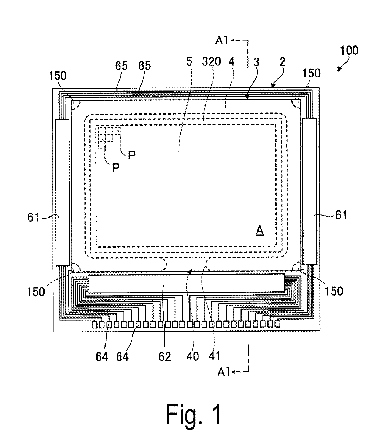
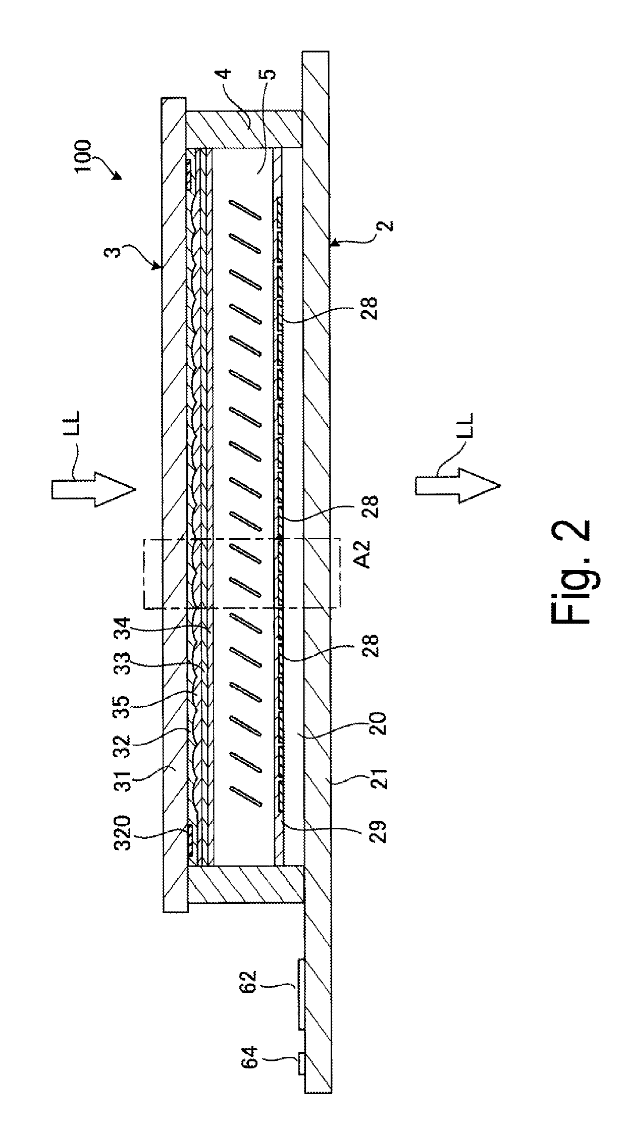
[0034]FIG. 1 is a schematic plan view of a liquid crystal display device in a first exemplary embodiment. FIG. 2 is a cross-sectional view of the liquid crystal display device illustrated in FIG. 1, and is a cross-sectional view taken along with a line A1-A1 in FIG. 1.

[0035]A liquid crystal display device 100 illustrated in FIGS. 1 and 2 includes an element substrate 2 (first substrate) having transmissivity, a counter substrate 3 (second substrate) that is disposed opposite to the element substrate 2 and has transmissivity, a frame-shaped sealing member 4 disposed between the element substrate 2 and the counter substrate 3, and a liquid crystal layer 5 surrounded by the element substrate 2, the counter substrate 3, and the sealing member 4. The liquid crystal display device 100 is a transmissive-type liquid crystal display device. In the exemplary embodiment, as illustrated in FIG. 2, the liquid crystal display device 100 modulates light LL incident from th...

second exemplary embodiment

[0109]Next, a second exemplary embodiment of the invention will be described.

[0110]FIG. 8 is an enlarged cross-sectional view of an element substrate provided in a liquid crystal display device in the second exemplary embodiment. FIG. 9 is a schematic diagram illustrating light passing through the liquid crystal display device illustrated in FIG. 8.

[0111]The exemplary embodiment is identical to the first exemplary embodiment described above except mainly for that a counter substrate does not include the microlens array and an element substrate includes the microlens array.

[0112]Note that, differences between the second exemplary embodiment and the above-described exemplary embodiment will be mainly described in the following description, and the same matters will not be described. The same configurations as those in the first exemplary embodiment described above are provided with the same reference signs in FIGS. 8 and 9.

[0113]A liquid crystal display device 100A illustrated in FIG....


PUM

PropertyMeasurementUnit
refractive indexaaaaaaaaaa
angleaaaaaaaaaa

Abstract

A first substrate includes a base material having transmissivity, a light-shielding body having a grid pattern in a plan view seen from a thickness direction of the base material, a pixel electrode, a first insulator having transmissivity that overlaps the light-shielding body in the plan view and is disposed between the base material and the pixel electrode, and a second insulator having transmissivity that overlaps the pixel electrode in the plan view and is disposed in contact with the first insulator between the base material and the pixel electrode. The second insulator has a refractive index greater than a refractive index of the first insulator. An interface between the second insulator and the first insulator has an inclined portion inclined away from a central axis along a thickness direction of the second insulator from the incident side of light toward an emitting side.

Description

BACKGROUND1. Technical Field[0001]The invention relates to a transmissive-type liquid crystal display device and an electronic apparatus.2. Related Art[0002]A liquid crystal display device has been typically used as a light bulb in a liquid crystal projector.[0003]For example, JP-A-2002-91339 discloses a liquid crystal display device that includes a plurality of pixel electrodes, a thin film transistor (TFT) array substrate including a TFT and wiring, a counter substrate including a counter electrode, and liquid crystals sandwiched between the TFT array substrate and the counter substrate. The TFT array substrate provided in the liquid crystal display device includes a plurality of opening regions through which light passes and a boundary region surrounding the opening region in a plan view. The pixel electrodes are disposed in the opening region. The wiring and the TFT are disposed in the boundary region. An optical surface for refracting light that is deviated from the opening reg...

Claims


Application Information

Patent Timeline
Patent Type & Authority Applications(United States)
IPC IPC(8): G02F1/1362G02F1/1335H04N9/31
CPCG02F1/136209G02F1/133526H04N9/3197G02F2203/01G02F2201/123H04N9/3105
Inventor HARUYAMA, AKIHIDE
Owner SEIKO EPSON CORP
Why Eureka
Try Eureka