

Cable connector assembly
- Summary
- Abstract
- Description
- Claims
- Application Information
AI Technical Summary
Benefits of technology
Problems solved by technology
Method used
Image

Examples
Embodiment Construction
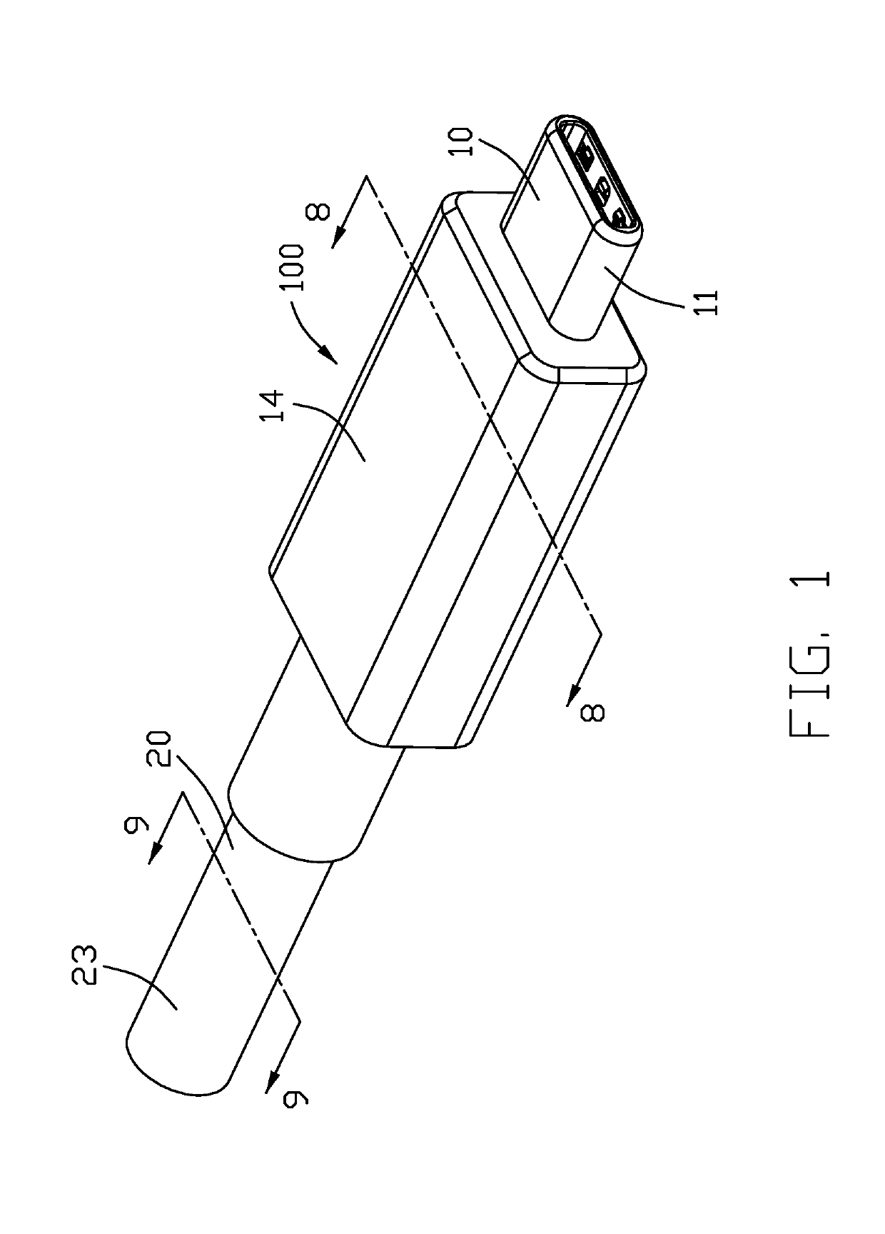
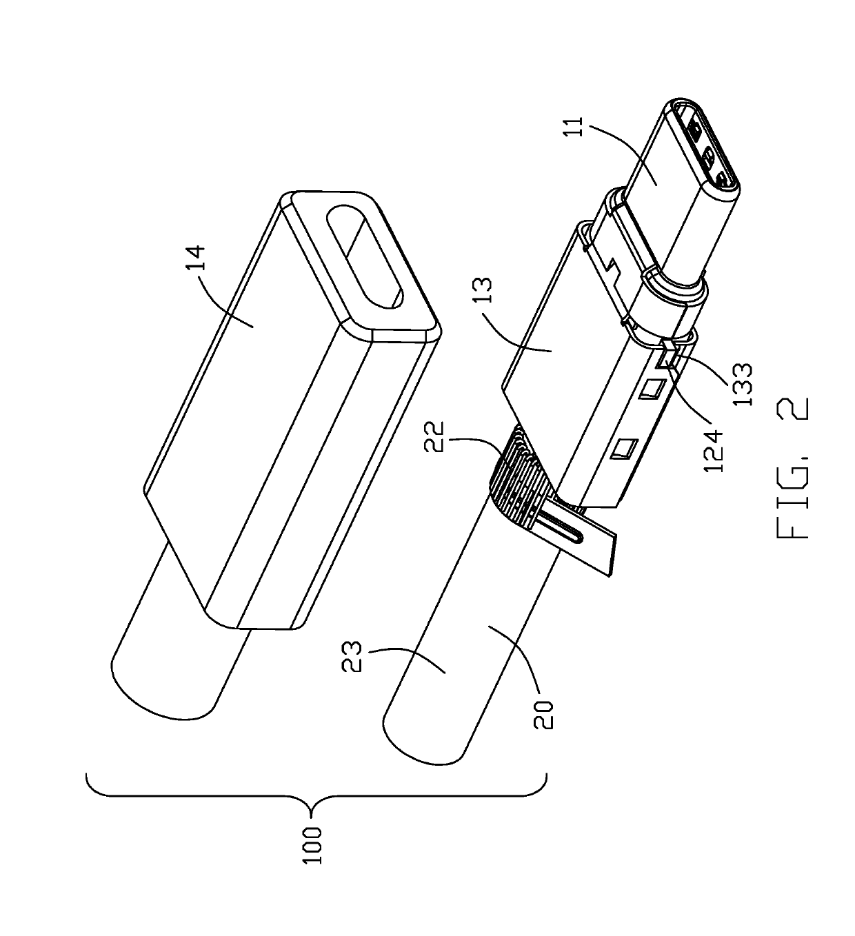
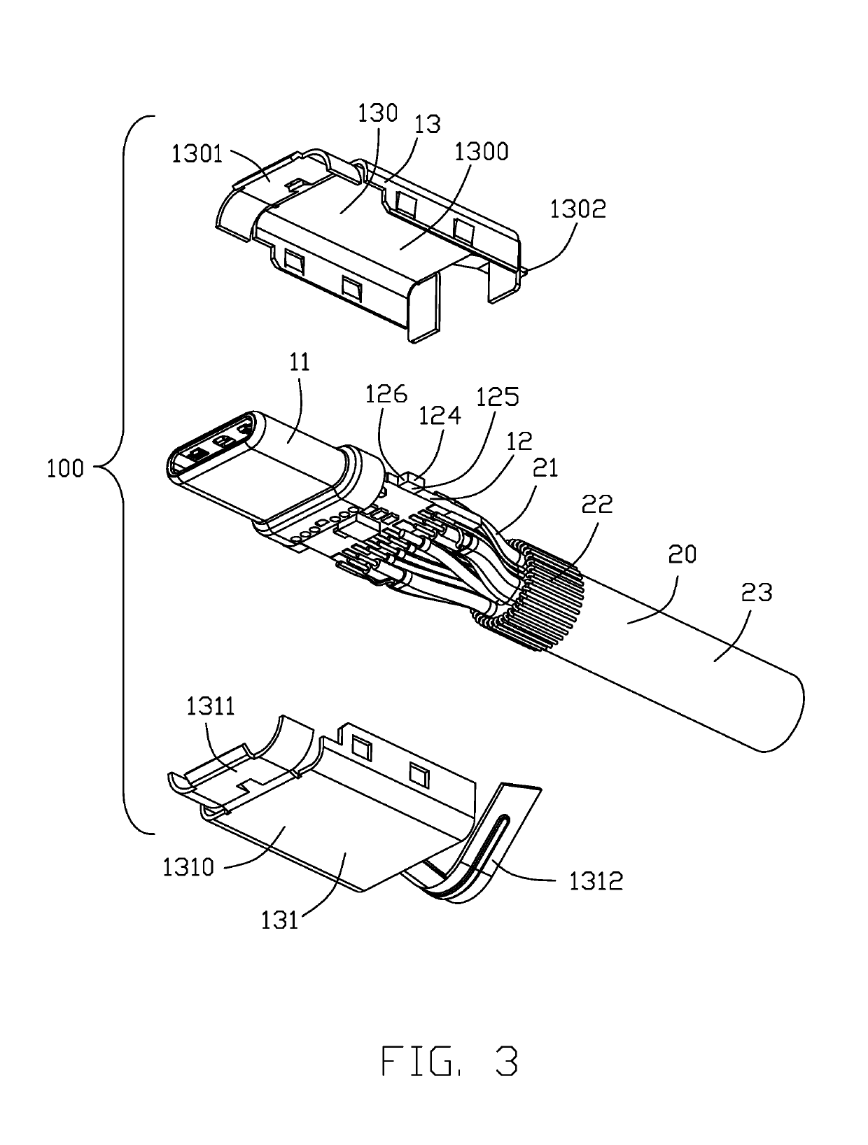
[0026]Reference will now be made in detail to a first embodiment of the present invention. Referring to FIGS. 1 to 9, a cable connector assembly 100 includes a electrically connector 10 and a cable 20 connected with the electrically connector 10. The electrical connector 10 includes a mating plug 11 mated with a mating connector, a circuit board 12 connected with the mating plug 11 and the cable 20, a metal housing 13 disposed outside the circuit board 12, and a outer housing 14 disposed outside the metal housing 13. In this embodiment, the electrical connector 10 conforms to the USB C specification, and it can be mated with the mating connector in two opposite directions.
[0027]The mating plug 11 includes an insulative housing 110, a plurality of terminals received in the insulative housing 110 that are spaced in two rows in the up and down direction, and a metal housing 112 disposed outside the insulative housing 110. One end of each terminal 111 is received in the insulative housi...
PUM
 Abstract
Description
Claims
Application Information