
Vacuum plasma reactor

a plasma reactor and vacuum technology, applied in nuclear reactors, greenhouse gas reduction, nuclear engineering, etc., can solve the problems of insufficient conformity of the stack of electrically conductive plates in the normal plane of the side parts, limited current loading capacity, and higher electromagnetic forces acting on the device, so as to reduce attractive forces, reduce the uneven current distribution of skin effects, and increase the loading capacity of the device

Active Publication Date: 2019-08-22
ROSSIJSKAJA FEDERATSIJA OT IMENI KOTOROJ VYSTUPAET GOSUDARSTVENNAJA KORPORATSIJA PO ATOMNOJ EHNERGII ROSATOM
View PDF1 Cites 0 Cited by
  • Summary
  • Abstract
  • Description
  • Claims
  • Application Information

AI Technical Summary

Benefits of technology

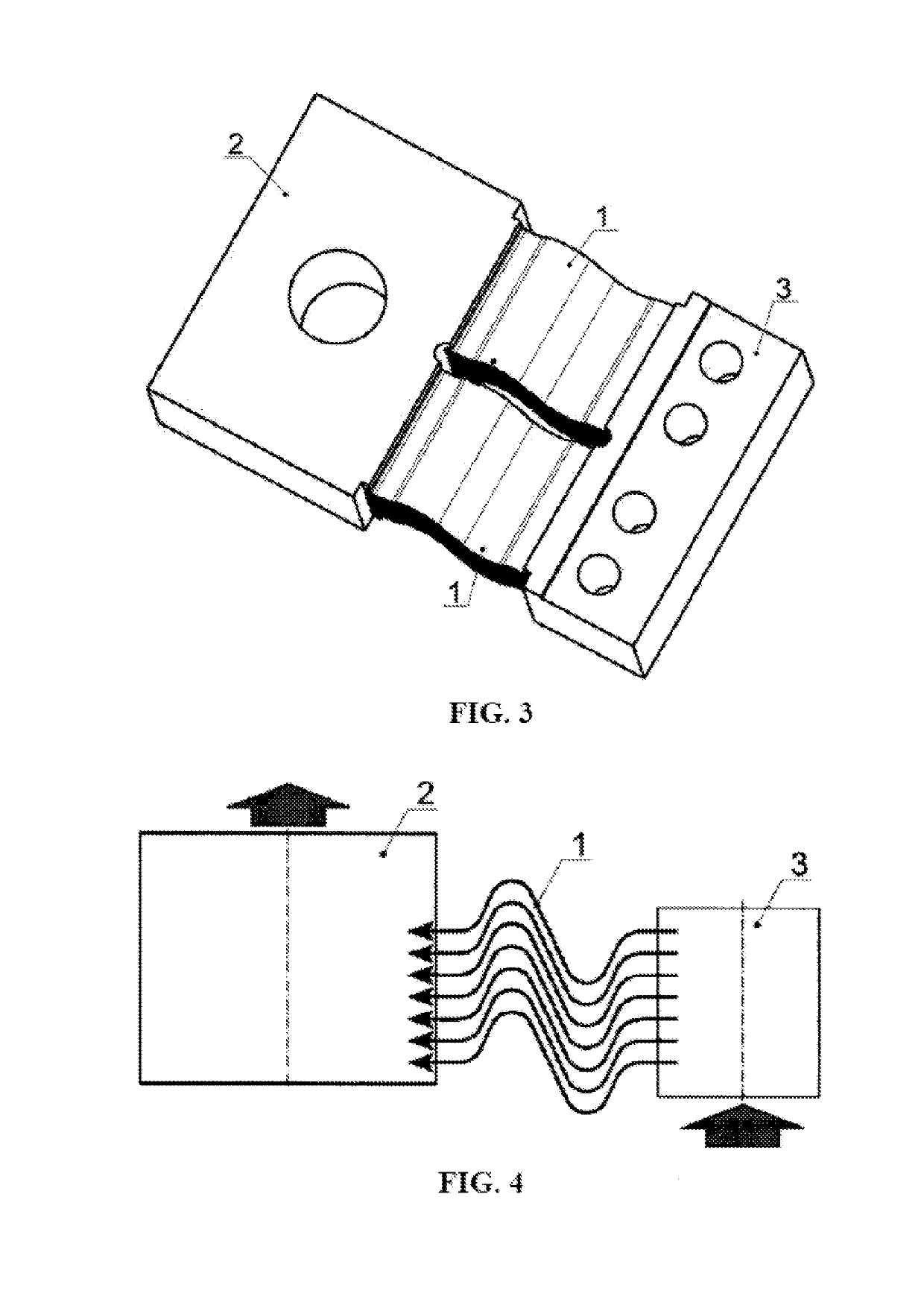
The present invention improves the current-loading capacity of a device used in a nuclear fusion reactor. It achieves this by minimizing the uneven current distribution among the electrically conductive plates through the use of two stacks with mirror symmetry and plates mounted along the generatrix in a plane parallel to the flange contact surfaces. This reduces the force of attraction between the outermost and center plates and ensures a substantially identical skin effect on all the plates. The invention also enables a Z-shaped connection scheme, which ensures as even as possible distribution of current among plates. These improvements increase the loading capacity of the device or reduce its dimensions while keeping the same load capacity as in the prior art.

Problems solved by technology

In the known device, due to perforations and folds in the plates, the stack of electrically conductive plates is insufficiently compliant in the direction normal to the plane of the side parts.
In addition, as far as the electrically conductive plates have vertical sections guiding electrical current perpendicularly to the main (toroidal) magnetic field component, this can result in higher electromagnetic forces acting on the device.
The drawback of the known device is that in a case of plasma disruption it has a limited current loading capacity when a current flows therethrough.
Therefore, the current loading capacity of the known device is limited by the compliance of the stack of electrically conductive plate elements, the magnetic field toroidal component of a nuclear fusion reactor, and by the presence of electrically conductive regions of the device which are perpendicular to the magnetic field.
The drawback of the known device is its reduced current loading capacity while nonpermanent (alternating or pulse) current flowing therethrough.
A further drawback of the known device is the reduced current loading capacity associated with a local increase in current density of electrically conductive plates appearing at junction (transition) points between the plates and the flanges, i.e., the most proximate points to current supply and drainage sites.

Method used


Image

  • Vacuum plasma reactor
  • Vacuum plasma reactor

Examples


Embodiment Construction

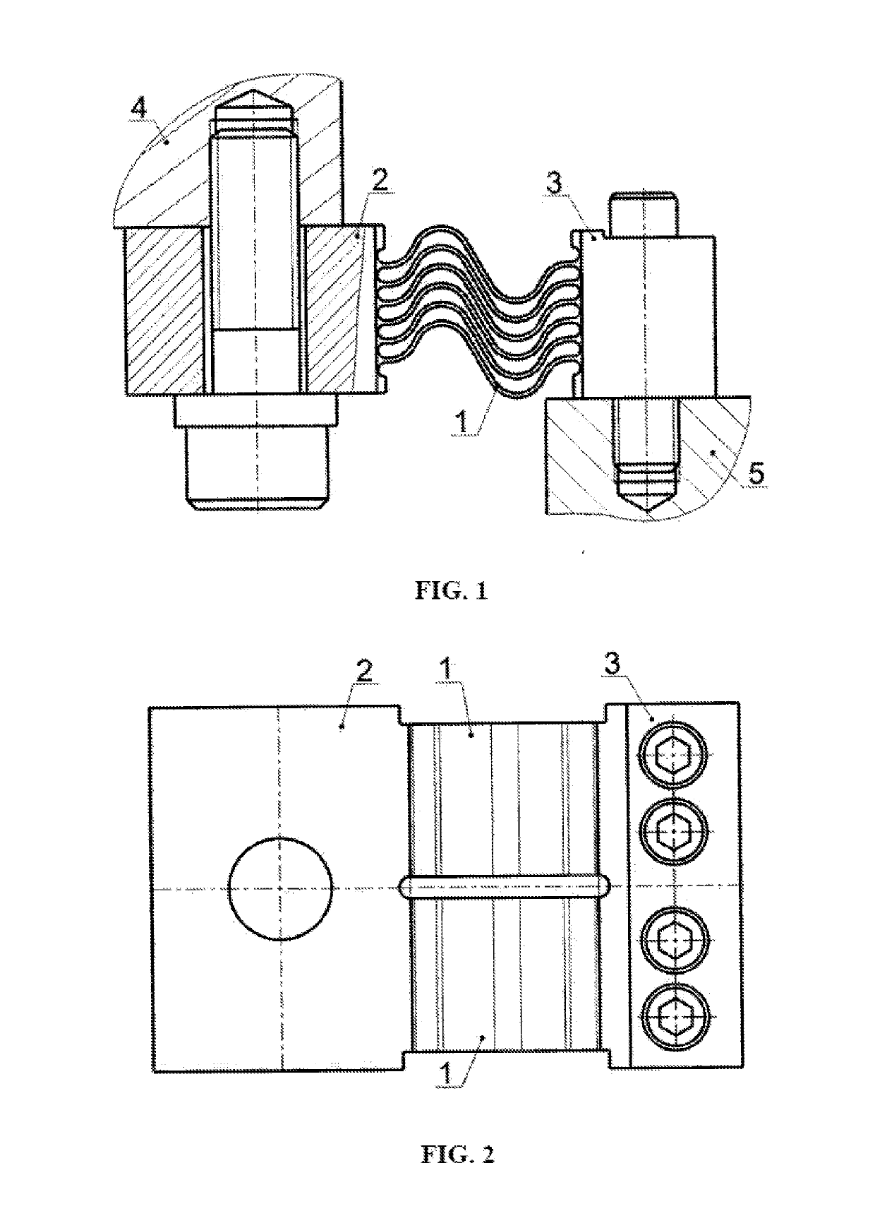
[0017]A device for electrically connecting components situated inside a nuclear fusion reactor chamber to a vacuum vessel of the reactor comprises two identical stacks of electrically conductive plates 1 and flanges 2, 3 for attachment to a vacuum vessel 4 and a component 5 situated inside a chamber, respectively. Said stacks of electrically conductive plates are mounted with mirror symmetry about a line that passes through the centers of symmetry of the flanges 2, 3. The electrically conductive plates 1 are in the shape of a symmetrical wave having at least one full period. Based on the layout needs, surfaces of the electrically conductive plates 1 can be in the shape of a symmetrical wave having more than one full period. In each stack, the electrically conductive plates 1 are nested one inside another by means of tongues and corresponding slots and jointed to the flanges 2, 3 for attachment to the component 4 situated inside the chamber and the vacuum vessel 5, for instance, by m...


PUM


Abstract

A device for electrically connecting components situated inside a nuclear fusion reactor chamber to the vacuum vessel of the reactor has two identical stacks of electrically conductive plates. The electrically conductive plates are in the shape of a symmetrical wave having at least one full period. The plates in a stack are nested one inside another and are connected to flanges for attachment to a component situated inside the chamber and to the vacuum vessel. The stacks of electrically conductive plates are mounted with mirror symmetry about a line that passes through the centers of symmetry of the flanges. The device ensures a substantially identical skin effect on all of the electrically conductive plates. In addition, the force of attraction between the outermost and center plates (the force of attraction between conductors carrying unidirectional currents) is reduced and a uniform current density distribution in each electrically conductive plate is provided.

Description

FIELD OF THE INVENTION[0001]The invention relates to the thermonuclear fusion and can be used in devices for electrically connecting components situated inside a nuclear fusion reactor chamber to the vacuum vessel of the reactor.BACKGROUND OF THE INVENTION[0002]It is known the device for electrically connecting components situated inside the nuclear fusion reactor chamber to the vacuum vessel of the reactor, comprising electrically conductive plates, nested in one stack, with differently directed surface areas provided between flanges for attachment to the component situated inside the chamber and to the vacuum vessel (International Atomic Energy Agency (MAFAT3), Vienna, 2002 ITER TECHNICAL BASIS, ITER EDA Documentation series No. 24, Plant Description Document, Chapter 2.3, Page 10-2.3.4.3 Electrical Connection, Figure 2.3.4-4 One Strap of the Electrical Connection).[0003]In the known device, the surface of plates with differently directed surface areas is L-shaped and is perforate...

Claims


Application Information

Patent Timeline
Patent Type & Authority Applications(United States)
IPC IPC(8): G21B1/17
CPCG21B1/17G21B1/13Y02E30/10
Inventor KOLGANOV, VLADIMIR YURYEVICHPODDUBNYY, IVAN IGOREVICHKIRILLOV, SERGEY YURYEVICHTROFIMOVICH, PYOTR DMITRYEVICH
Owner ROSSIJSKAJA FEDERATSIJA OT IMENI KOTOROJ VYSTUPAET GOSUDARSTVENNAJA KORPORATSIJA PO ATOMNOJ EHNERGII ROSATOM
Learn More