

Mirror for a solar reflector, method of mirror assembly and management system in a solar field
a technology of solar reflector and mirror, applied in the direction of instruments, lighting and heating apparatus, optical elements, etc., can solve the problems of reducing the production of these systems, reducing efficiency, and reducing the amount of sunlight reflected on the receiver, so as to reduce the cost of the plant, increase the degree of automation, and reduce the effect of plant cos
Active Publication Date: 2019-08-29
FUNDACION TEKNIKER +1
View PDF15 Cites 0 Cited by
- Summary
- Abstract
- Description
- Claims
- Application Information
AI Technical Summary
Benefits of technology
The patent is about a new technology called autonomous heliostats, which makes it easier and more cost-effective to install and commission solar reflectors. The technology helps with information gathering during mounting, positioning, and installation, and also helps monitor the transport stages of the mirrors. Overall, this leads to significant cost reductions for solar power plants.
Problems solved by technology
The energy production of these systems decreases as the mirrors lose their properties (they become dirty, they move in their supporting structure, they lose their orientation, etc.) and therefore the amount of sunlight reflected on the receiver is lower, which also lowers efficiency.
All the foregoing systems that reflect the state of the art have a drawback, which consists in having to use external devices that require additional installation tasks such as, for example, the proper installation of the sensor on some kind of element of the reflector (for example, on the supporting structure of the mirrors) and the proper referencing of the sensor with respect to the mirror.
This additional handling when manufacturing the reflector implies additional costs both in time and resources, as well as in the availability of the system.
Furthermore, there exists a risk due to the handling itself of the mirror and the structure thereof, a risk that can lead to moving or deforming the mirror and its supporting structure consequently bringing about loss of orientation thereof, thus forcing repositioning of the mirror, resulting in additional cost.
Another risk, albeit to a lesser extent, consists in that scratching or breaking can damage the surface of the mirror.
The heliostats contained in these documents present all the problems listed above but do not particularly describe mirrors with sensors that have been integrated during the manufacturing process of the mirrors prior to installing the mirror in a solar reflector but rather a heliostat with an already installed mirror on which a camera is mounted and there are no devices other than a camera.
They refer to mirrors with two layers and not three layers such as those of the present invention, since it is necessary to place the camera behind the reflecting layer, and should there be a protective layer behind the reflecting layer, this would mean rupturing said protective layer consequently damaging the newly installed mirror, increasing the exposure of the interior layers and reducing their level of protection, which is neither practical nor is it safe.
Furthermore, mounting the camera would be difficult requiring difficult calibration steps.
Said documents do not describe a mirror with an integrated sensor, but rather an encapsulated camera mounted on the back of a mirror, with the consequent drawbacks derived from the handling of the camera on the mirror that is already installed in the heliostat, in addition to possible defects in said mounting and encapsulation, which can bring about less protection for the camera and lead to environmental problems that can cause deterioration such as abrasion (sand), exposure to ultraviolet light, saline surroundings, etc.
The foregoing drawbacks are mainly due to the fact that, as already anticipated, implementing the systems described in said documents requires incorporating additional elements to the mirror during the installation in the field or the adjustment phase that require painstaking installation, alignment, mounting and commissioning processes, which must be performed in the field with limited means and under uncontrolled conditions that may affect the accuracy and functional nature of the systems.
For example, aforementioned patent ES2534037 relates to the need to align the optical axis of a camera with the normal vector of the mirror perpendicular to the plane of the mirror, which must be performed after assembling the mirror in the heliostat, requiring tasks (deviation to be corrected in the calibration) and equipment (collecting and inserting machine) that are additional to the mere installation of the mirror on the heliostat, a tedious process with limited means resulting in high costs and poor quality.
Method used
View moreImage
Smart ImageViewing Examples

Examples
first embodiment
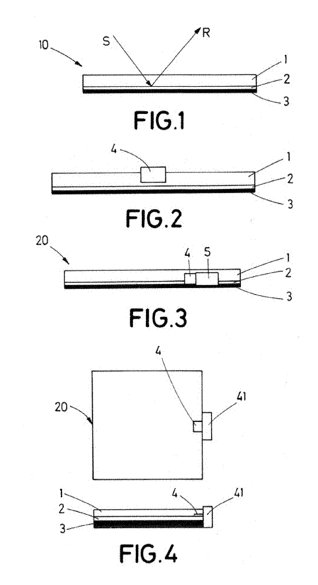
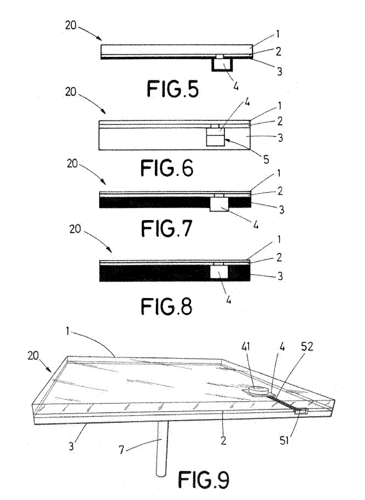
[0103]FIG. 2 shows a side view of a mirror with an integrated sensor.
second embodiment
[0104]FIG. 3 shows a side view of a mirror with an integrated sensor.
third embodiment
[0105]FIG. 4 shows a plan view and a side view of a mirror with an integrated sensor.
Login to View More PUM
 Abstract
A mirror for a solar reflector comprising has at least one sensor integrated in the body of the mirror itself, the body of the mirror being all the layers of the mirror. At least one processor is integrated in the body of the mirror, associated with the sensor, thus generating an intelligent device and an intelligent mirror or smart mirror. A method of assembling the mirror itself and a management system for mirrors that make up a solar field is provided.
Description
TECHNICAL FIELD[0001]The present invention, in general, relates to a mirror for a solar reflector comprising at least one sensor integrated in the body of the mirror itself, the body of the mirror being understood as all the layers that comprise the same. Furthermore, integrating at least one processor in the body of the mirror, associated with the sensor, gives rise to an intelligent device and thus, to an intelligent mirror or smart mirror. The invention also relates to a method of assembly of the mirror itself and to a management system for mirrors that make up a solar field.[0002]The invention is applicable in the field of solar energy and in particular that of concentrating solar energy.BACKGROUND OF THE INVENTION[0003]Numerous types of solar reflectors are known in the state of the art, which include one or more mirrors or facets such as those shown in FIGS. 19 to 24. A solar reflector is made up of the mirror or mirrors themselves, the structure on which the mirror or mirrors...
Claims
Login to View More Application Information
Patent Timeline
 Patent Type & AuthorityApplications(United States)
IPC IPC(8): F24S50/00F24S23/70
CPCF24S23/82F24S50/00Y02E10/40Y02E10/52H02S40/22F24S23/70G02B5/0808G02B17/06
InventorBURISCH, MICHAELSÁNCHEZ, MARCELINOVILLASANTE CORREDOIRA, CRISTÓBALARANZABE BASTERRECHEA, ESTÍBALIZ
OwnerFUNDACION TEKNIKER