Radar-assisted tracking of mobile devices to improve the communication link in high frequency communciation

a mobile device and tracking technology, applied in the field of mobile network telecommunications, can solve the problems of significant reduction of the communication link between the tp and the ue, and difficulty in high frequency operation, and achieve the effect of improving the communication link and improving the communication link

Active Publication Date: 2019-08-29
SONY CORP
View PDF0 Cites 7 Cited by
  • Summary
  • Abstract
  • Description
  • Claims
  • Application Information

AI Technical Summary

Benefits of technology

[0010]Further, use of pulse signals, such as radar pulses, pilot pulses or the like which allow for determination of the likely presence of a UE and / or tracking information associated with the UE (e.g., position, direction of movement, rate / speed of movement and the like) has the additional benefit of saving beam synchronization power consumption. Such a power consumption savings is especially beneficial at the UE, since reducing synchronization power consumption provides for additional battery life.
[0012]In specific embodiments of the invention, radar or other forms of pulse signals are used to assist in handover procedures (i.e., moving a data stream from a first direction to a second direction). The handover procedure may be transmission point-to-transmission point (TP-to-TP) (e.g., base station-to-base station (BS-to-BS), access point-to-access point (AP-to-AP) or the like) or internal with a single BS employing multiple radio heads (radio head-to-radio head) or the like. In this regard, as a result of determining the likely presence of a UE in a specific area based on the echo signals and confirming the presence, neighboring TPs / BSs / APs / radio heads may receive presence information that indicates the presence of the UE in the specific area. As a result of receiving the presence information, the neighboring TPs / BSs / APs / radio heads know the proximate direction at which the UE is likely located and can increase beam sweep frequency in that specific area (i.e., in the proximate direction at which the UE is located) in order to expedite initializing a communication link with the UE. In this regard, the information resulting from employing radar or some other pulse signal serves to assist in accelerating handover and / or reconnection procedures, which may be more prevalent in higher frequency operating communication networks due to the aforementioned shadowing phenomena.
[0022]In specific related embodiments of the method, assisting in the transmission point-to-transmission point handover further includes increasing beam sweep frequency in the predetermined area based on the likely presence of the one of the UE within the predetermined area. In such embodiments of the method, increasing beam sweep frequency in the predetermined area may include increasing transmission of the pulse signals in the predetermined direction associated with the predetermined area based on the likely presence of the one of the UE within the predetermined area.

Problems solved by technology

However, higher frequency operation also presents challenges, which are not necessarily present when operating at conventionally lower frequency.
One of the additional challenges presented by higher frequency operation comes from the fact that the electromagnetic waves (EM-waves) tend to behave different at higher frequencies.
Shadowing refers to the inability of a signal to reach its intended destination, such as a UE, because obstacles located between the UE and transmission point (e.g., BS) block or otherwise affect the wave propagation.
In other instances, the mere rotation of the UE may dramatically change the angle of arrival and / or departure from the UE and, if the transmission point (i.e., beam tracking in the BS or the like) cannot catch up with the rotational speed of the UE, the communication link between the TP and the UE may be significantly reduced and / or lost.
A challenge in such higher frequency mobile networks is that when shadowing occurs and a BS / TP loses the connection with the UE or is about to lose the connection, one of the alternative BSs / TPs needs to be ready to make a connection with the UE.

Method used


Image

  • Radar-assisted tracking of mobile devices to improve the communication link in high frequency communciation
  • Radar-assisted tracking of mobile devices to improve the communication link in high frequency communciation
  • Radar-assisted tracking of mobile devices to improve the communication link in high frequency communciation

Examples


Embodiment Construction

[0032]Embodiments of the present invention now may be described more fully hereinafter with reference to the accompanying drawings, in which some, but not all, embodiments of the invention are shown. Indeed, the invention may be embodied in many different forms and should not be construed as limited to the embodiments set forth herein; rather, these embodiments are provided so that this disclosure may satisfy applicable legal requirements. Like numbers refer to like elements throughout.

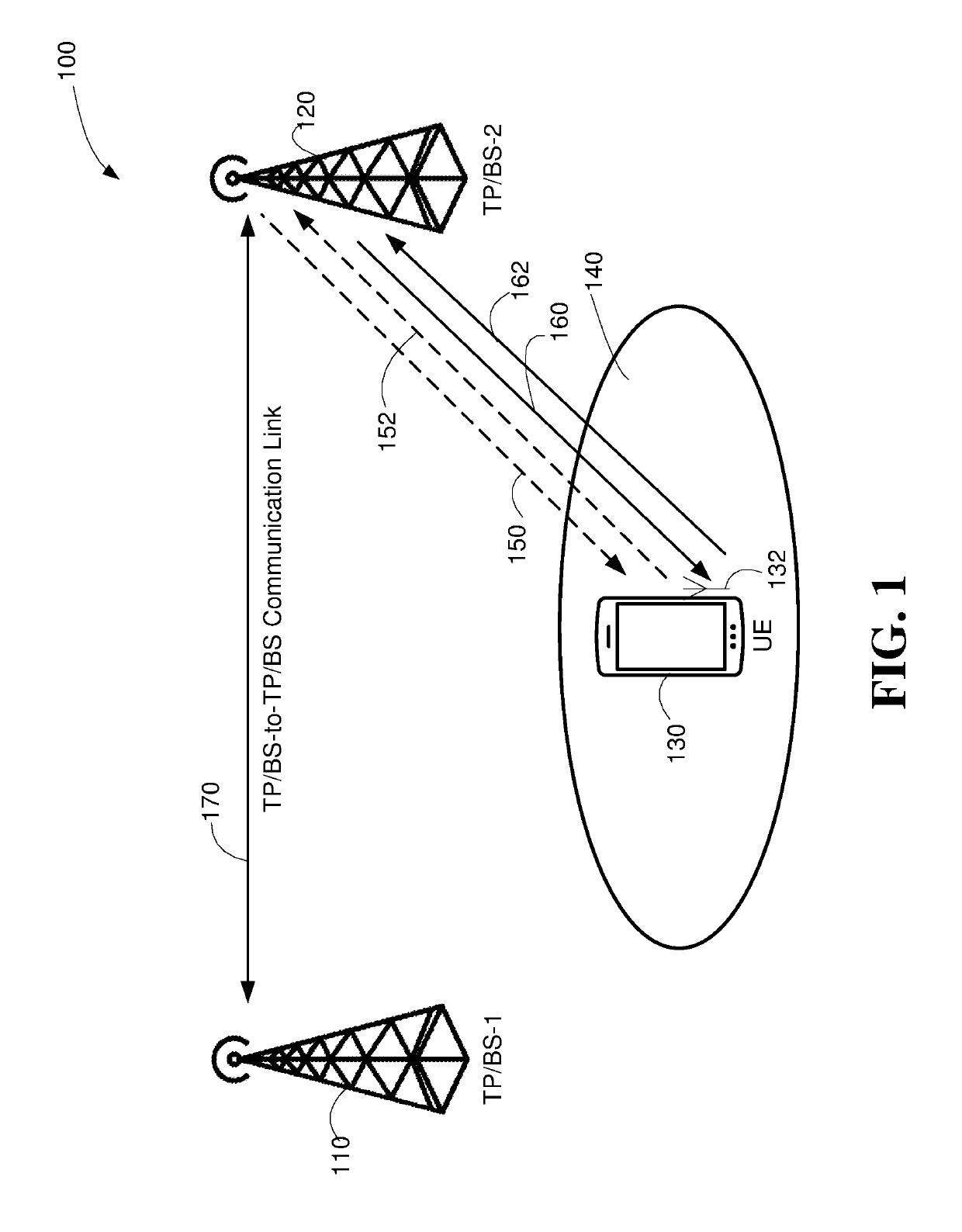
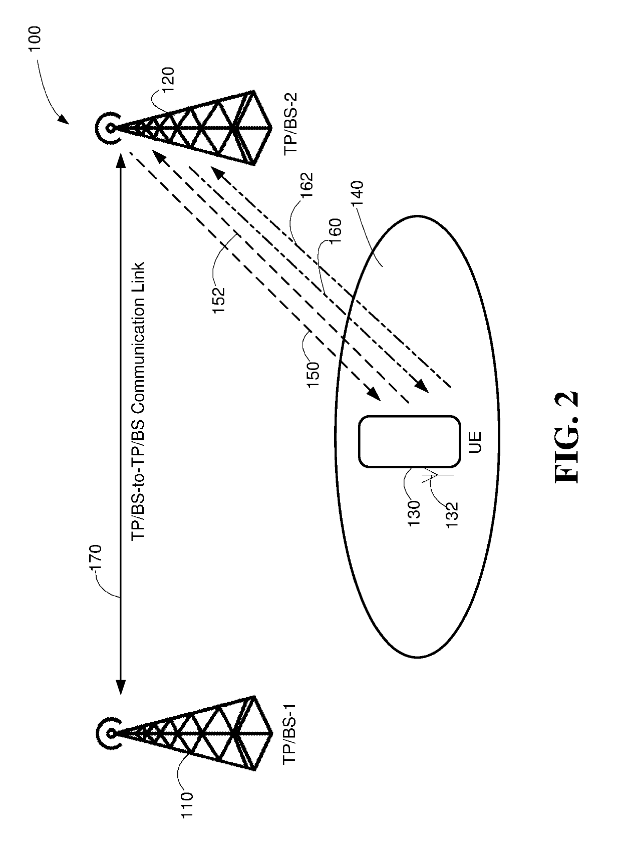
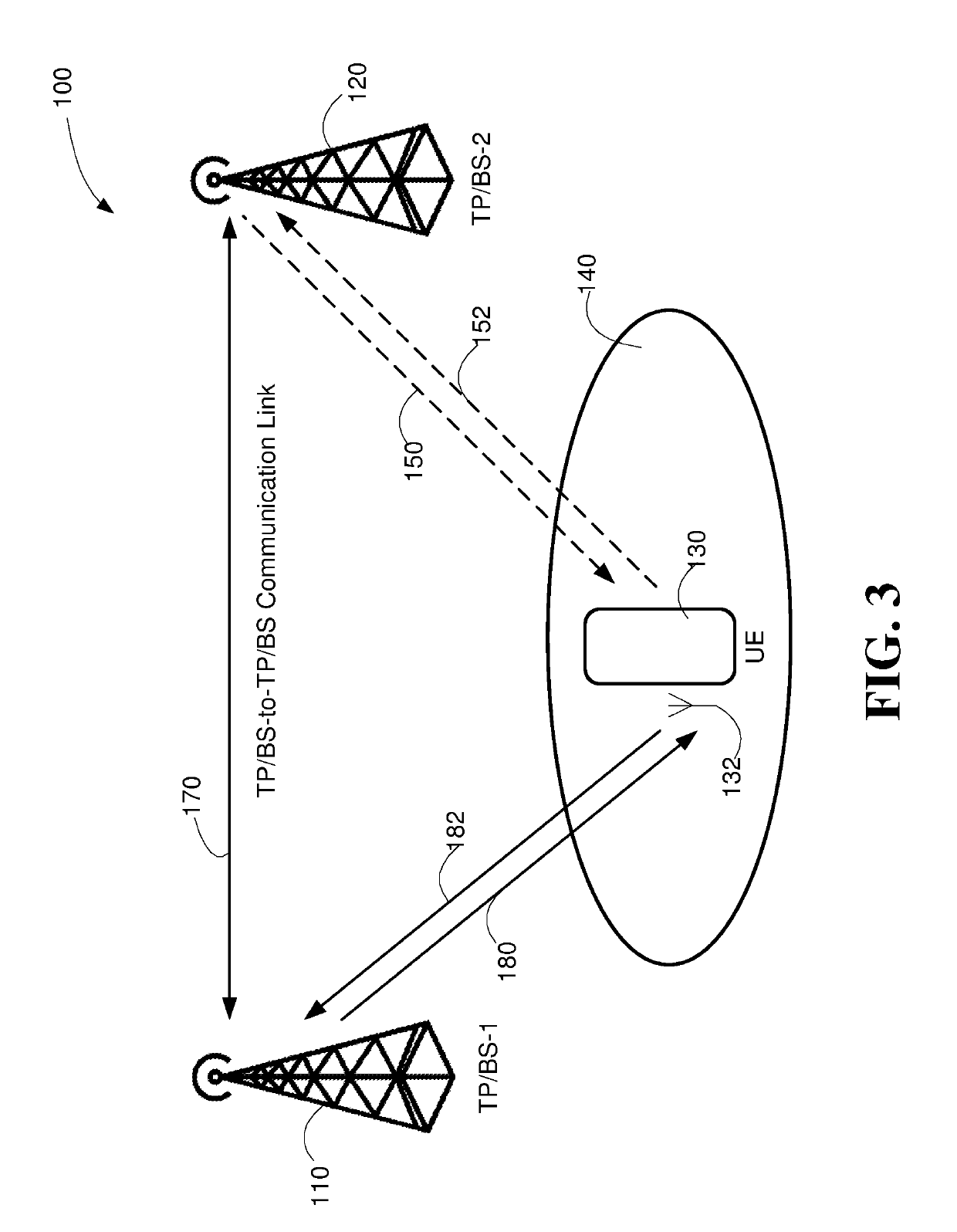
[0033]A mobile device may be referred to as a node or user equipment (“UE”). For the purpose of sending or receiving data, the device may connect to a wireless local area network (“WLAN”) or a mobile communication network (including evolution of 3GPP, LTE releases and 5th Generation (“5G”) New Radio (NR) releases). Any network described herein may have multiple transmission points. Transmission points may include any node or sub-node capable of transmitting a wireless data stream, including, but not l...


PUM


Abstract

Pulse signal transmission, such as radar pulses or the like are used in a high frequency mobile communication network as a means for determining or assisting in determining the likely presence of User Equipment (UE) and / or tracking UE in a predetermined area. As a result of determining the likely presence of UE and / or tracking UE, such information may be used to expedite either a handover or establish re-connection within the communication network. In this regard, more targeted beam sweeps or more frequent sweeps can be made in the direction where the UE has been determined to likely be present in order to hasten the establishment of the communication link between the targeted transmission point, such as a Base Station (BS) or the like, or reconnection to the existing transmission point.

Description

FIELD OF THE INVENTION[0001]In general, embodiments of the invention relate to mobile network telecommunications and, more particularly, methods, apparatus, systems and the like for using radar to track the position or movement of User Equipment (UE) in a communication network by determining the likely presence of the UE in a predetermined area covered by the network. In specific embodiments of the invention such presence information and / or tracking information may be used to assist in a handover procedure and / or establishing a re-connection in the event a connection has been or is about to be lost.BACKGROUND[0002]In impending mobile networks, such as 3GPP (Third Generation Partnership Project) NR (New Radio) or the like, the use of higher frequency operation, such as operation at or above 20 GHz (Giga Hertz), is being considered. In one such mobile network, use of millimeter (mm) waves, which occupy the frequency spectrum from 30 GHz to 300 GHz is considered. Such higher frequency ...

Claims


Application Information

Patent Timeline
Patent Type & Authority Applications(United States)
IPC IPC(8): G01S13/72G01S13/76
CPCG01S13/76G01S13/72G01S13/003G01S13/10G01S13/86H04W36/32G01S2013/9316G01S7/412H04W4/029H04W16/28H04W64/003
Inventor BENGTSSON, ERIKYING, ZHINONG
Owner SONY CORP
Why Eureka
Try Eureka