Velocity sensing for aircraft

a technology of velocity sensing and aircraft, applied in the direction of vehicle position/course/altitude control, process and machine control, instruments, etc., can solve the problems of reynolds number turbulence, inability of traditional sensors to measure the smallest fluctuations in turbulent flows, and significantly underestimate the scalar rate of dissipation, etc., to enhance the stabilization capability of the control system, reduce power consumption, and improve the effect of robust control system

Active Publication Date: 2019-08-29
INSTRUMEMS INC
View PDF8 Cites 4 Cited by
  • Summary
  • Abstract
  • Description
  • Claims
  • Application Information

AI Technical Summary

Benefits of technology

[0014]In addition to their measurement capabilities, the small size of the nanowire sensors makes them lightweight and low power. Thus, these real time velocity sensors can be leveraged for a variety of measurement and control applications. Furthermore, the MEMS-based fabrication process allows for batch production with a high-volume yield of identical sensors, allowing multiple sensors to be assembled in a sensor suite to measure multiple components of velocity.
[0015]In addition to measuring turbulence, the performance of these nanoscale probes fulfills a growing need to develop more robust control systems for flying machines. Currently the stabilization control systems for flying machines consists of an array of auxiliary sensors which measure the vehicle's state relative to the external environment. Examples of these sensors may include an accelerometer, gyroscope, GPS, and downward facing camera (optical flow). These sensor measurements are typically used to estimate the vehicle's state (angular orientation, angular velocity, position, and velocity). Then a control algorithm implemented on an onboard flight computer uses this estimation of the vehicle state to adjust outputs

Problems solved by technology

As described in the study, it was observed that cold wire attenuation has widespread effects on most aspects of the measurements, resulting in the variance and the scalar rate of dissipation being significantly underestimated.
One of the largest challenges to a comprehensive understanding of high Reynolds number turbulence is the inability for traditional sensors to measure t

Method used


Image

  • Velocity sensing for aircraft
  • Velocity sensing for aircraft
  • Velocity sensing for aircraft

Examples


Embodiment Construction

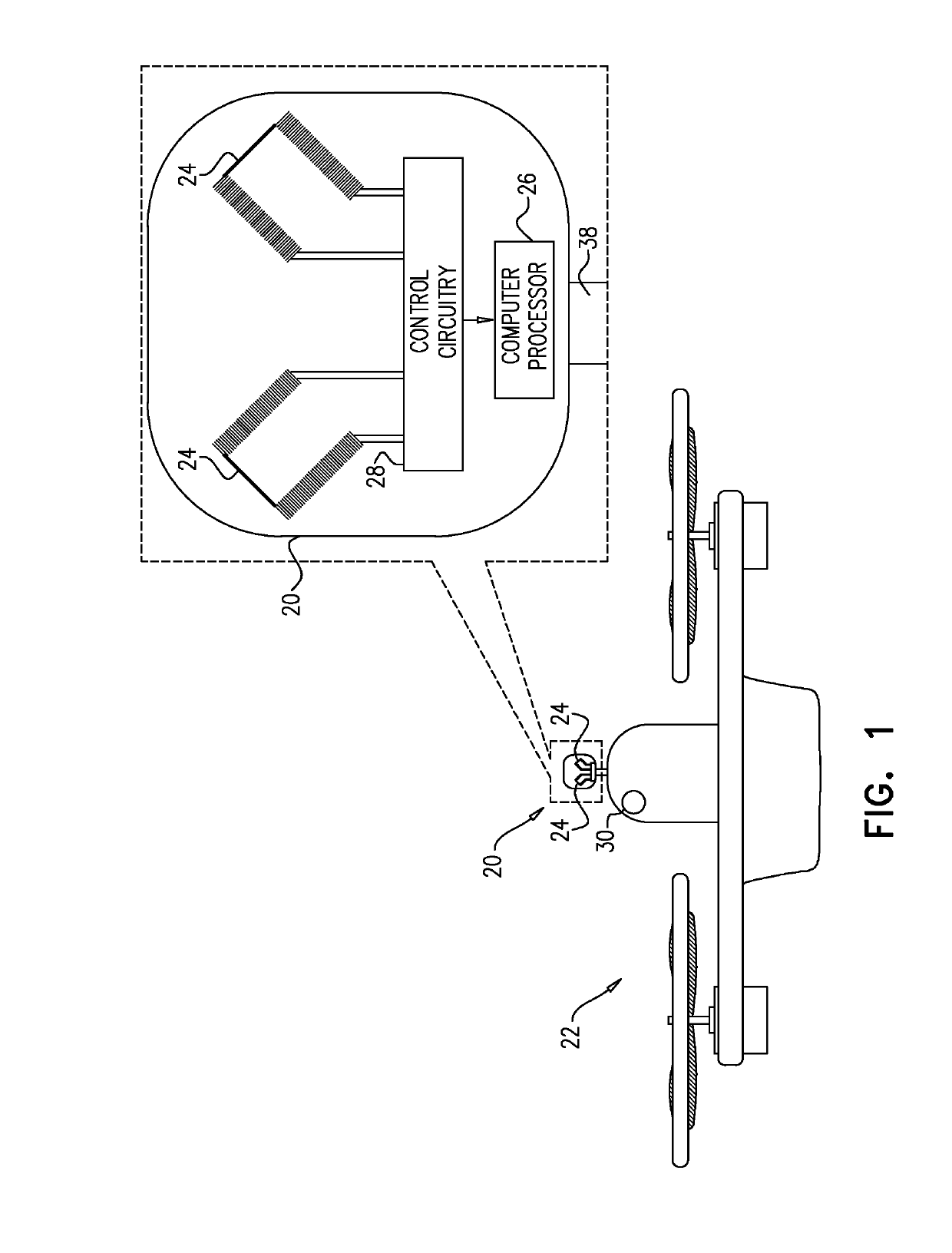
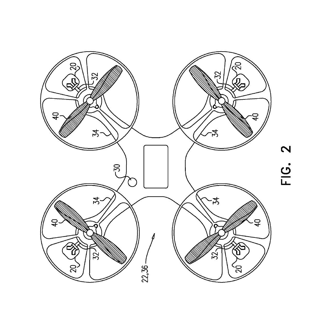
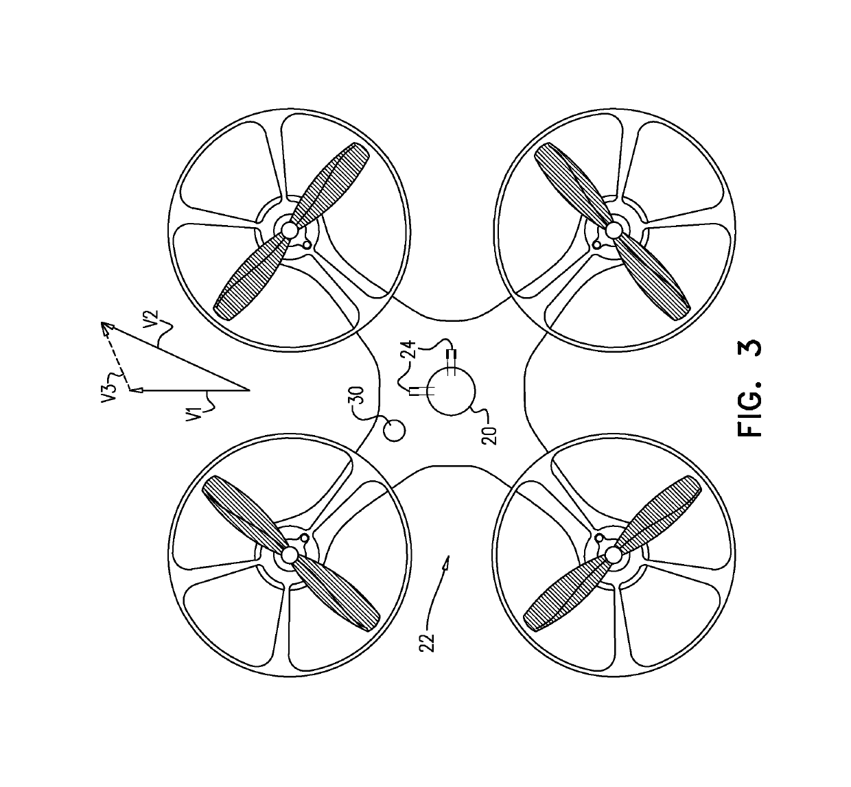
[0109]Reference is now made to FIG. 1, which is a schematic illustration of a sensor 20 on a flying machine 22, the sensor including a plurality of nanowires 24 and a computer processor 26, in accordance with some applications of the present invention. Sensor 20 is typically mounted on an external surface of flying machine 22, e.g., a fixed-wing aircraft, single rotor aircraft, or multi-rotor aircraft. Each nanowire measures a value of local air velocity relative to flying machine 22. Nanowires 24 are dimensioned for measuring velocity, are capable of measuring high frequency velocity changes, and can be operated using a constant current anemometer (CCA) or a constant temperature anemometer (CTA). Control circuitry 28 in sensor 20 typically operates nanowires 24 using constant temperature anemometry. An active feedback loop keeps each nanowire 24 at a constant temperature, and a current flowing through each nanowire 24 is altered accordingly so as to ensure that each nanowire 24 rem...


PUM


Abstract

A method for measuring a windspeed vector is described. A true airspeed vector of a flying machine is measured while the machine is in flight using one or more nanowires on the flying machine. Each nanowire is configured to measure a value of local air velocity relative to the flying machine. A velocity of the flying machine relative to the ground is measured while the machine is in flight, and then (a) the true airspeed vector is subtracted from (b) the velocity of the flying machine relative to the ground. Other applications are also described.

Description

CROSS-REFERENCE TO RELATED APPLICATIONS[0001]The present application claims the priority of U.S. 62 / 636,270 to Arwatz, filed Feb. 28, 2018 entitled, “Velocity sensing for aircraft,” which is incorporated herein by reference.FIELD OF THE INVENTION[0002]The present invention relates to nanowire sensors for sensing velocity of a fluid flow.BACKGROUND[0003]The dissertation of Gilad Arwatz, Ph.D., entitled “Investigations of the fundamentals of passive scalar dynamics using nano-sensing devices,” Princeton University, 2015, which is incorporated herein by reference, describes turbulence as being the core of numerous investigations over several decades. Among the wide spectrum of turbulence aspects in the study described in the dissertation, the study focuses on temperature as a passive scalar advected in a turbulent velocity field. In this study, fundamental flow quantities are revisited by investigating statistically homogeneous and isotropic turbulence, with an imposed mean cross-strea...

Claims


Application Information

Patent Timeline
IPC IPC(8): G05D1/08G01P5/10B64C39/02B64C17/00
CPCB64C2201/162B64C2201/141G05D1/0816B64C39/024B64C17/00B64C2201/027G01P5/10B64C2201/108G01P5/12G05D1/046G05D1/0808B64U2201/00B64U10/13B64U30/20
Inventor ARWATZ, GILAD
Owner INSTRUMEMS INC
Why Eureka
Try Eureka