
Delivering radiation

a radiation and radiation technology, applied in the field of radiation and radiation application, can solve the problems of large shutters that cannot be taken to remote locations without significant expense, and cannot meet the requirements of delivering radiation,

Active Publication Date: 2019-08-29
SOURCE PRODN & EQUIP
View PDF0 Cites 4 Cited by
  • Summary
  • Abstract
  • Description
  • Claims
  • Application Information

AI Technical Summary

Benefits of technology

The system described in this patent is a radiography camera system that uses a smooth drive cable to move the camera into different positions. The system includes a crank arm that moves the cable forward and reverse, with a control assembly housing and a drive mechanism that allows the cable to be wound and unwound smoothly. The control assembly housing and drive mechanism are designed to prevent any interference with the smooth movement of the cable. The technical effect of this system is to provide a more reliable and efficient mechanism for positioning the camera during a medical examination.

Problems solved by technology

Normal X-ray generators are limited in the energy that can be produced because of limitations in the voltage that can practicably be applied to the X-ray tube.
Furthermore, a typical X-ray machine is large and requires a power source, it cannot be taken to remote locations without significant expense.
The disadvantage of this approach is that a massive shutter must be manipulated and must have very precise dimensions to avoid gaps through which radiation could emerge in the “closed” position.
This is also susceptible to being fouled by dirt and foreign matter during the normal course of use, which could prevent the shutter from closing properly and thereby failing to accomplish its intended purpose of shielding the emergent beam of radiation.
Although this approach eliminates the need to manipulate a massive shield and its associated drawbacks, the disadvantage of this approach is that there are shielded elements both in front of and in back of the source which can interfere with the performance of the radiographic exposure.
However, the additional shielding necessary to compensate for the shielding missing from the “U” channel adds appreciably to the weight of the container.
A disadvantage of this design was that it permits the locking pins to be engaged at any position along the driving cable as well, thereby locking the source in an exposing position.
Perry describes deficiencies of the prior art coupling devices.
This arrangement does not, however, provide for the automatic locking of the radioactive capsule within the storage unit, upon its return to its stored position within the storage unit.

Method used


Image

  • Delivering radiation
  • Delivering radiation
  • Delivering radiation

Examples


embodiment 200

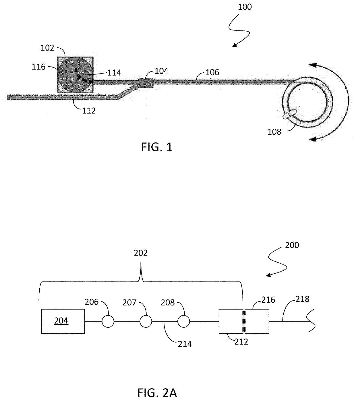
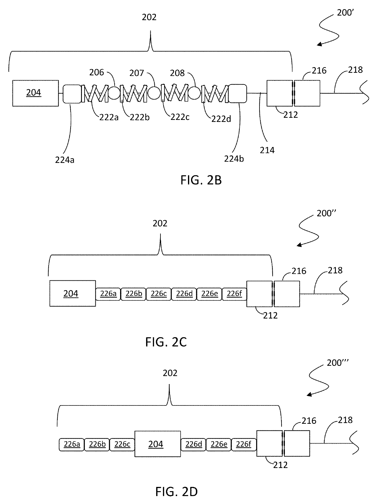
[0068]Referring to FIG. 2A, an embodiment 200 of a source assembly 202 includes a source capsule 204, a plurality of beads 206-208, and a connector 212. The beads 206-208 may be made out of tungsten or some other suitable material. The source capsule 204 is a sealed container containing a gamma-emitting source material, such as gamma-emitting radiation sources, such as sources containing 192Iridium, 60Cobalt, 75Selenium, 170Thulium and / or 169Ytterbium. Of course, other possible gamma-emitting sources may be used. The source capsule 204 may be attached to a flexible cable 214 to which the beads 206-208 and the connector 212 are also attached. In an embodiment herein, the flexible cable 214 may be type 316SS aircraft cable, although of course other types of cable may be used. Attaching the beads 206-208 to the flexible cable 214 reduces the possibility of a disconnect due to fractured tungsten (or similar) parts that are only attached to a cable at each end of the parts. As described ...

first embodiment

[0077]Referring to FIG. 5A, the J-channel 114 and the shielding 116 are shown with the source assembly 202 partially inserted into the J-channel 114 in connection with an automatic securing mechanism. The J-channel 114 includes a ramp 502 that is used to secure the source assembly by securing the source capsule 204 when the source assembly 202 is inserted sufficiently into the J-channel 114. The ramp 502 allows the source capsule 204 to pass as the source capsule 204 is being pushed by the drive cable 218 toward the terminal end of the J-channel 114. FIG. 5B shows the source assembly 202 in a locked position where the ramp 502 prevents the source capsule 204 from moving away from the terminal end of the J-channel. In an embodiment herein, an operator may confirm that the source capsule 204 is in a locked position by attempting to gently crank the source capsule 204 out of the J-channel 114. FIG. 5C illustrates an operator releases the source assembly 202 from the J-channel by actuat...

second embodiment

[0078]Referring to FIG. 6A the J-channel 114 and the shielding 116 are shown with the source assembly 202 partially inserted into the J-channel 114 in connection with an automatic securing mechanism. In this embodiment, there is no ramp. Instead, the J-channel 114 includes a pivot bar 602 that is used to secure the source assembly by securing the bead 208 when the source assembly 202 is inserted sufficiently into the J-channel 114. The pivot bar 602 pivots from a first position shown in FIG. 6A to a second position shown in FIG. 6B as the source assembly 202 is being pushed by the drive cable 218 toward the terminal end of the J-channel 114. FIG. 6B shows the source assembly 202 in a locked position where the pivot bar 602 secures the bead 208 to prevent the source assembly 202 from moving away from the terminal end of the J-channel. The pivot bar 602 includes a hooked end portion 604 that retains the bead 208. As with the embodiment discussed above, an operator may confirm that the...


PUM


Abstract

A radiography camera system includes an exposure container made from radiation shielding material and having a curved channel therein that terminates inside the exposure container, a first conduit portion having a first end coupled to the exposure container, a switch coupled to a second end the first conduit portion, a second conduit portion having a first end coupled to the switch, a guide tube coupled to the switch, a crank coupled to a second end of the second conduit portion, and a cable disposed in the crank and having a connector for a source assembly on an end thereof, the cable actuating the switch to cause the cable to feed through one of: the first conduit portion or the guide tube when the crank unwinds the cable. The exposure container may be made from depleted uranium, tungsten, and / or lead. The curved channel may be J-shaped.

Description

CROSS-REFERENCE TO RELATED APPLICATIONS[0001]This application claims priority to U.S. provisional patent application No. 62 / 406,670 filed on Oct. 11, 2016 and titled “DELIVERING RADIATION” and on U.S. provisional patent application No. 62 / 420,106 filed on Nov. 10, 2016 and titled “DELIVERING RADIATION”, both of which are incorporated by reference herein.TECHNICAL FIELD[0002]This application relates to the field of radiography and the application of radiation, and more particularly to the field of manipulating a source in connection with the application of radiation.BACKGROUND OF THE INVENTION[0003]In radiography, a source of penetrating photon radiation (X-ray or gamma ray) is placed on one side of a specimen and a detector of radiation (often film, but many types of detectors are used) is placed on the other side. In passing through the specimen, the radiation is attenuated by the material along the beam path. Thicker and denser material will attenuate the radiation to a greater de...

Claims


Application Information

Patent Timeline
IPC IPC(8): G21F5/015G21F3/00G21F1/12A61B6/10
CPCG21F5/015G21F3/00A61B6/107A61B6/4258G21F1/125G03B42/02
Inventor DICHARRY, RICHARD DONALDMILLER, WILLIAM KIRKJOHNSON, STEVEN ANDREW
Owner SOURCE PRODN & EQUIP
Learn More