
Reinforcing structure for a wind turbine blade

a technology of reinforced structure and wind turbine blade, which is applied in the manufacture of final products, machines/engines, other domestic articles, etc., can solve the problems of strip cracking along the groove(s), and achieve the effect of enhancing resin infusion and maximising resin spa

Active Publication Date: 2019-09-05
VESTAS WIND SYST AS
View PDF2 Cites 8 Cited by
  • Summary
  • Abstract
  • Description
  • Claims
  • Application Information

AI Technical Summary

Benefits of technology

The invention is a way to make a pultruded strip that can flex and conform to the curved shape of a mold or wind turbine blade shell. The strip has grooves that allow it to bend and flex in a perpendicular direction, and these grooves also help the resin to flow between the pultrusions and into the mold. The grooves can be on the upper or lower surface of the strip, and they are designed to widen when the strip flexes. This design allows the strip to have a greater amount of space between the pultrusions, which increases the amount of resin that can flow into the mold. The resulting strip is stronger and lighter than traditional methods, and it can be used to reinforce wind turbine blade shells.

Problems solved by technology

In some cases, bending the strip along the one or more grooves may cause the strip to crack along the groove(s).

Method used


Image

  • Reinforcing structure for a wind turbine blade
  • Reinforcing structure for a wind turbine blade
  • Reinforcing structure for a wind turbine blade

Examples


Embodiment Construction

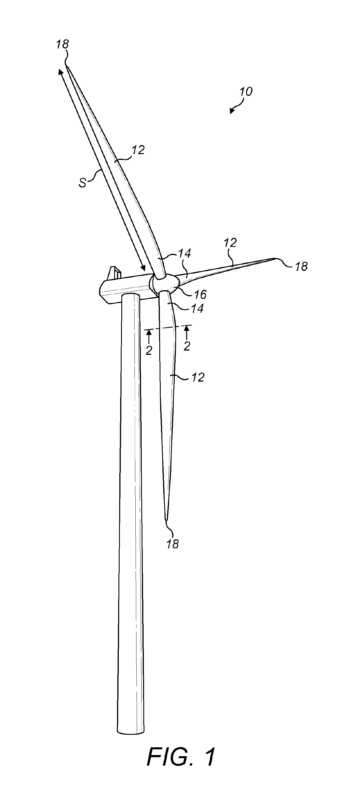
[0048]FIG. 1 shows a wind turbine 10 comprising a plurality of wind turbine blades 12. The blades 12 are connected at their respective root ends 14 to a wind turbine blade hub 16. Each blade 12 extends in a longitudinal or ‘spanwise’ direction S from its root end 14 to a tip end 18. Typically the blades 12 are substantially circular at their root ends 14, where they connect to the hub 16. The blades 12 then develop an airfoil profile in transverse cross-section moving in the spanwise direction S towards the tip 18.

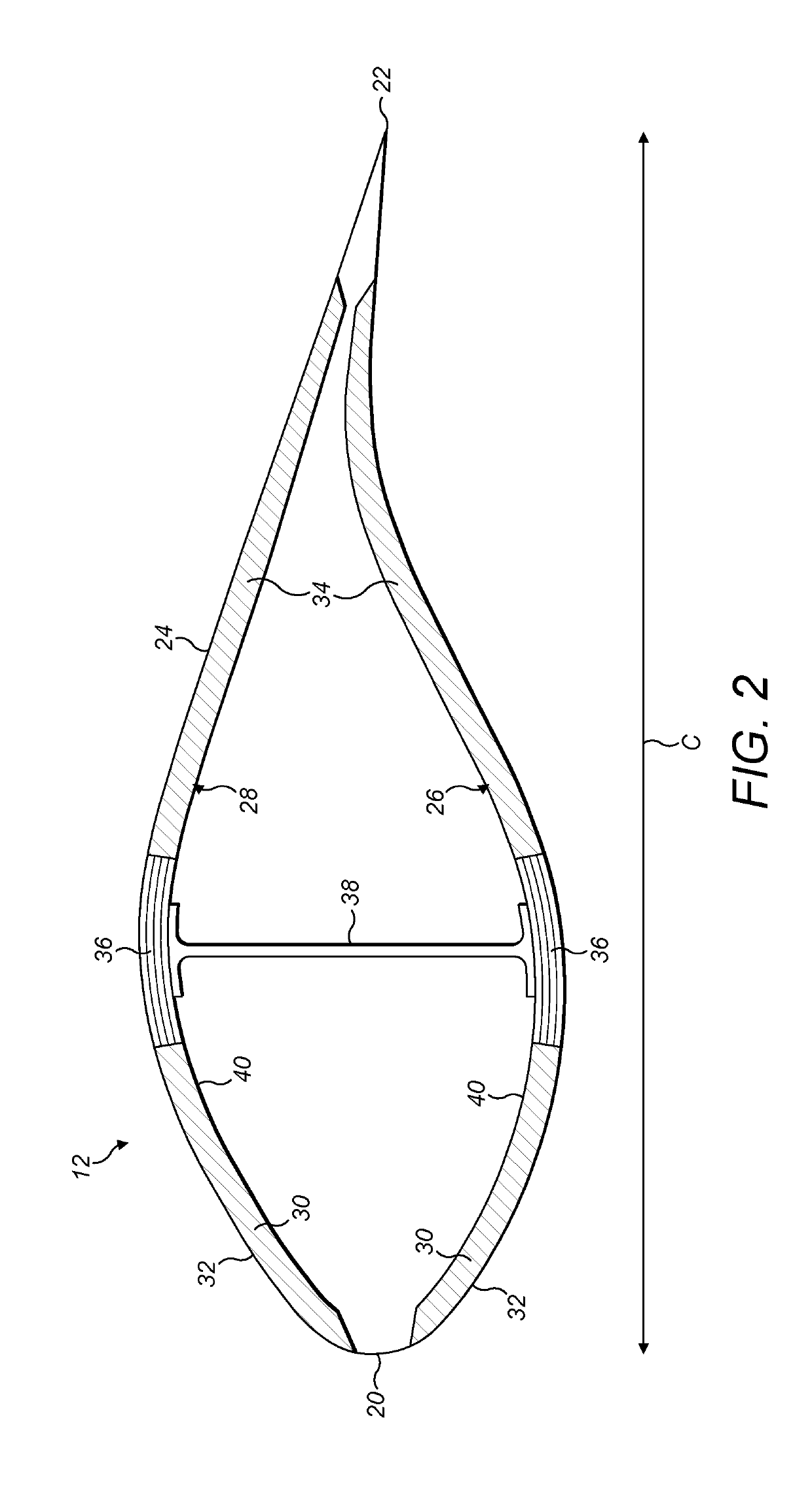
[0049]FIG. 2 is a schematic transverse cross-sectional view of one of the wind turbine blades 12 of FIG. 1, taken along the line 2-2 in FIG. 1. It can be seen from FIG. 2 that the blade 12 has an airfoil profile in this region. The blade 12 extends in a ‘chordwise’ direction C between a leading edge 20 and a trailing edge 22. The blade 12 comprises an outer shell 24, which in this example is formed from a windward half-shell 26 and a leeward shell 28 that are bonded togeth...


PUM

PropertyMeasurementUnit
lengthaaaaaaaaaa
lengthsaaaaaaaaaa
thicknessaaaaaaaaaa

Abstract

A reinforcing structure for a wind turbine blade A reinforcing structure for a wind turbine blade (12) is described. The reinforcing structure comprises one or more pultruded strips (42C) having spanwise grooves (54). The grooves (54) impart transverse flexibility to the strips (42C), allowing the strips (42C) to conform to the curvature of a wind turbine blade mould (44). An associated method of making a reinforcing structure for a wind turbine blade (12) is described. The method comprises providing an elongate mould (44) extending in a longitudinal direction and defining a mould surface at least part of which is concave-curved in transverse cross section. One or more pultruded strips (42C) with spanwise grooves (54) are arranged in the mould (44) to form the reinforcing structure. The pultruded strip(s) are bent along the grooves (54) so that they substantially conform to the transverse curvature of the mould surface. In preferred embodiments the reinforcing structure is a spar cap (36)

Description

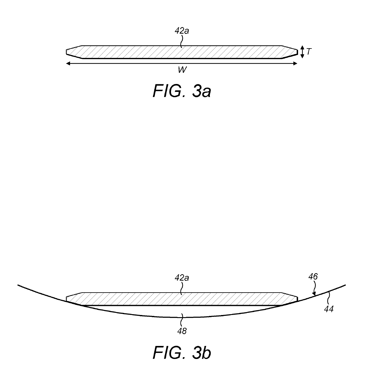
TECHNICAL FIELD[0001]The present invention relates generally to reinforcing structures such as spar caps for wind turbine blades, and to methods of making such reinforcing structures.BACKGROUND[0002]Modern wind turbine blades typically comprise a fibreglass outer shell and one or more load-bearing reinforcing structures such as spar caps. Spar caps are structural beams that typically run along the full length or a majority of the length of the blade and carry the bending loads. Spar caps are typically integrated with the outer shell of the blade, for example they may be embedded within the structure of the outer shell, or bonded to an inner surface of the shell.[0003]It is known to form spar caps from strips of fibre-reinforced polymeric material, such as carbon-fibre reinforced plastic (CFRP). For example, a known spar cap comprises a stack of substantially flat CFRP strips, which are bonded together by cured resin. The carbon strips are typically formed in a pultrusion process, wh...

Claims


Application Information

Patent Timeline
Patent Type & Authority Applications(United States)
IPC IPC(8): B29C70/34F03D1/06B29C70/44B29C70/52B29C70/54B29D99/00
CPCB29C70/342F03D1/0675B29C70/443B29C70/526B29L2031/085B29D99/001B29D99/0028B29C70/521B29C70/547B29C53/04Y02E10/72Y02P70/50
Inventor RANDALL, STEPHEN
Owner VESTAS WIND SYST AS
Learn More