
Mobile hydrogen dispenser for fuel cell vehicles

a fuel cell vehicle and hydrogen tank technology, applied in the direction of container filling under pressure, gearing, container discharging methods, etc., can solve the problems of inconvenient veering off a particular route, affecting the commercialization of hydrogen-fueled fuel cell vehicles, and disrupting the hydrogen availability of vehicle tanks

Active Publication Date: 2019-09-05
AIR LIQUIDE ADVANCED TECH U S
View PDF9 Cites 6 Cited by
  • Summary
  • Abstract
  • Description
  • Claims
  • Application Information

AI Technical Summary

Benefits of technology

The invention allows for automatic balancing of pressure between a source and a vehicle tank, which results in the flow of fluid being discontinued.

Problems solved by technology

While these permanent filling stations perform quite satisfactorily, it is recognized that station upsets may occur from time to time resulting a disruption of the availability of hydrogen for filling the vehicle tanks.
This may result in a customer arriving at the station only to find a technician at the site diagnosing or fixing the issue preventing operation of the station.
This is a problem if the vehicle tank does not contain enough hydrogen for the vehicle to reach the nearest station.
A related problem occurs when a driver neglects to drive to a filling station before the vehicle tanks is emptied of hydrogen.
This problem is sometimes referred to as “range anxiety” and may inhibit further commercialization of hydrogen-fueled fuel cell vehicles.
For areas that are served by filling stations, it may be inconvenient to veer off a particular route in between two destinations for the purpose of refilling the vehicle tank.
This adds greater expense, weight and complexity, requires a larger footprint, increases maintenance frequency and expense, and in the case of a photovoltaic cell array and associated battery, is subject to losing voltage sufficient to power the PLC during cloudy weather.
As a result, the mobile refueler is heavy enough to require that it either be towed by a commercial vehicle (such as a ¾ ton pick-up truck) or be borne by rail, ship, or other truck mounted systems.
Such a towed or transportation vehicle-borne mobile fueler is relatively expensive to manufacture and operate and may be difficult to maneuver into small spaces adjacent the vehicle to be filled.
Because the mobile refueler disclosed by U.S. Pat. No. 6,786,245 relies upon a PLC-controlled cascade fill, it is relatively more prone to equipment failure due to the presence of numerous valves, sensors, controllers, and associated instrumentation.
Such a mobile fueler is expensive to manufacture, is subject to a relatively greater frequency of maintenance, and may experience relatively more equipment failures in comparison to less complex, mechanically robust systems.
Such a mobile refueler is thus more apt to be unavailable to stranded customers due to the need for refilling.

Method used


Image

  • Mobile hydrogen dispenser for fuel cell vehicles
  • Mobile hydrogen dispenser for fuel cell vehicles
  • Mobile hydrogen dispenser for fuel cell vehicles

Examples


Embodiment Construction

[0028]When operation of a hydrogen filling station for filling hydrogen tanks of fuel cell vehicles must be stopped due to equipment failure, the primary maintenance goal is to return the station to full operation. In fulfillment of this goal, some repairs may require several hours to complete, and in rare cases, additional time may be required for a proper diagnosis of the problem. In the meantime, vehicle operators requesting a fill at the station may be stranded because the vehicle tank may not contain an amount of hydrogen that sufficient to drive the vehicle to a different, and operable, filling station. The mobile hydrogen dispenser of the present invention may be used to at least partially fill the tanks of these stranded vehicle operators so that they have at least enough hydrogen to drive to a nearby station for a more complete fill. The mobile hydrogen dispenser of the present invention may also be used to at least partially fill the tanks of fuel cell vehicles at hydrogen...


PUM


Abstract

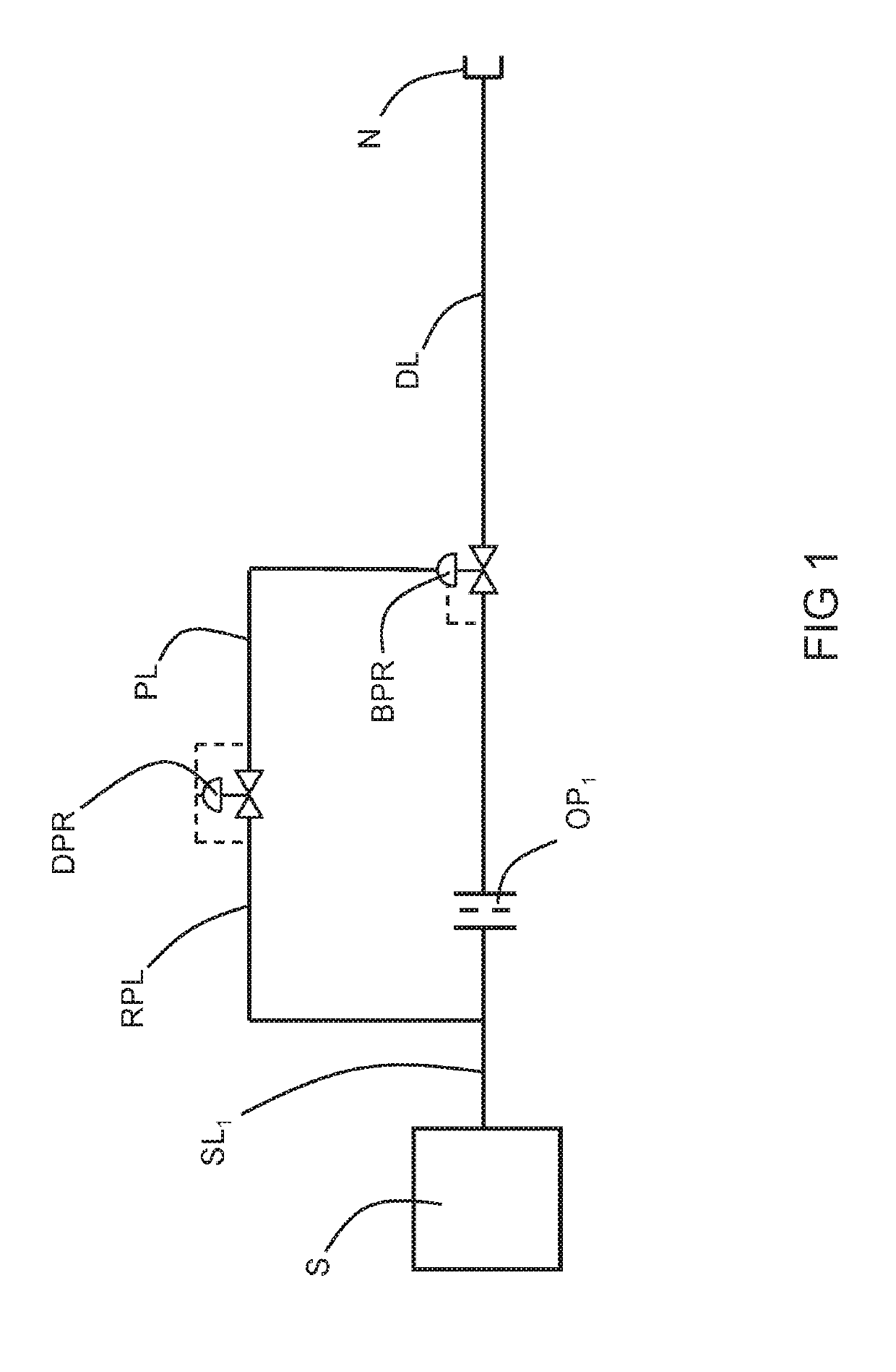
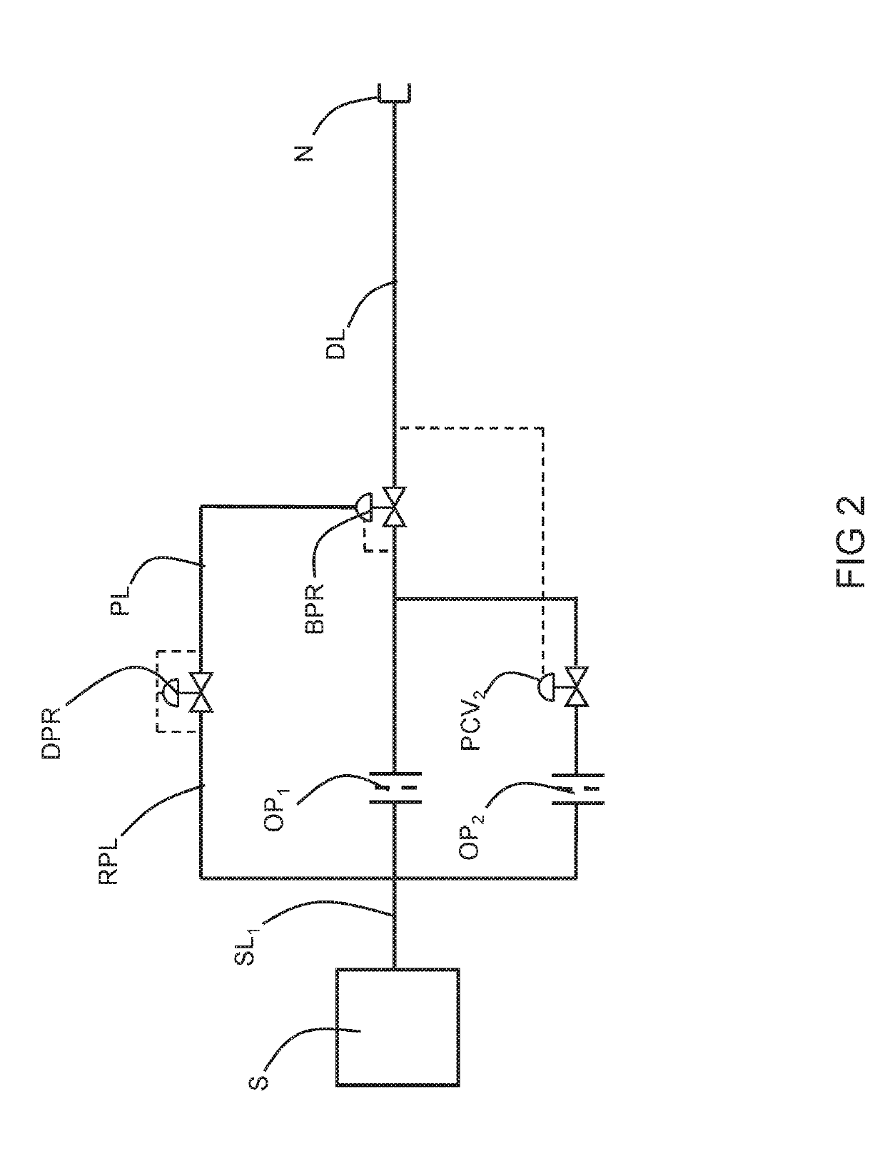
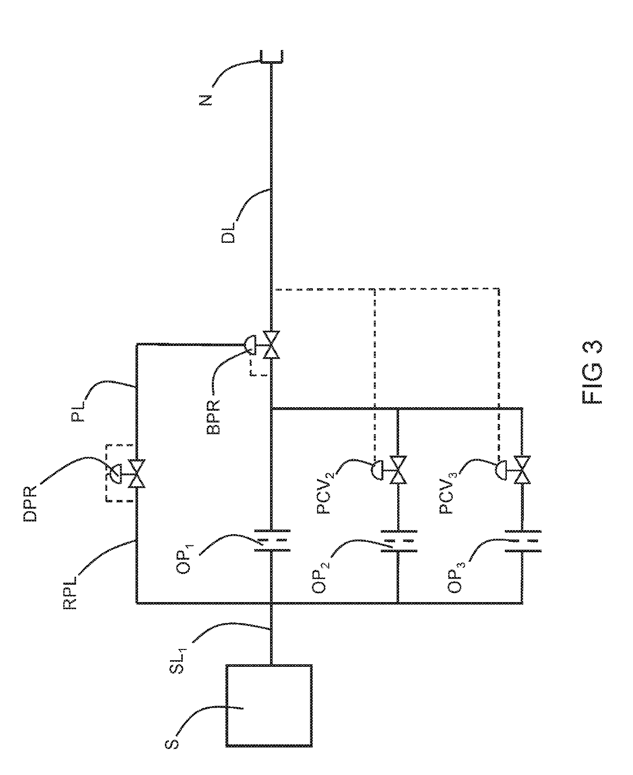
A mobile dispenser may be used to at least partially fill hydrogen tanks of fuel cell-powered vehicles. The dispenser uses a purely mechanical control of the fill using an orifice plate across which a pressure differential is maintained through use of a backpressure regulator whose reference pressure is controlled by a differential pressure regulator. Because it does need or use electrical power, it may be used in situations where no electrical power is available or convenient.

Description

CROSS-REFERENCE TO RELATED APPLICATIONS[0001]This application claims the benefit of U.S. Provisional Application No. 62 / 637,830, filed Mar. 2, 2018.BACKGROUNDField of the Invention[0002]The present invention relates to the filling of vehicle hydrogen tanks using a mobile gas dispenser.Related Art[0003]In an effort to boost utilization of sustainable fuels, such as hydrogen gas for use in fuel cell vehicles, several technologies have been proposed or implemented for achieving fills of the hydrogen tanks aboard such vehicles. One typical method includes a permanent filling station including relatively large storage tanks, one or more compressors, one or more buffer tanks, heat exchangers for cooling the compressed hydrogen, and instrumentation and valves for performing the filling of the vehicle tank in a controlled manner.[0004]While these permanent filling stations perform quite satisfactorily, it is recognized that station upsets may occur from time to time resulting a disruption o...

Claims


Application Information

Patent Timeline
IPC IPC(8): F17C5/06F17C13/02
CPCF17C5/06F17C13/025F17C2223/0123F17C2223/013F16H1/2818G05D7/03G05D16/024G05D16/028G05D16/16F17C5/007F17C2205/0338F17C2205/035F17C2221/012F17C2223/036F17C2225/0123F17C2225/036F17C2250/0626F17C2265/065F17C2270/0139Y02E60/32F17C13/00
Inventor LOPEZ, JORGE E.HARRIS, AARONNICKELL, CHADSCHMIDT, GERHARD M.OWENS, OWEN C.OLSSON, PER
Owner AIR LIQUIDE ADVANCED TECH U S
Learn More