Inner ring for a turbomachine, vane ring with an inner ring, turbomachine and method of making an inner ring

a technology of inner ring and turbomachine, which is applied in the direction of machine/engine, leakage prevention, engine manufacture, etc., can solve the problems of detrimental effect of turbomachine efficiency, and achieve the effect of reducing wall thickness, producing especially simple, and minimizing wall thickness

Active Publication Date: 2019-09-12
MTU AERO ENGINES GMBH
View PDF0 Cites 0 Cited by
  • Summary
  • Abstract
  • Description
  • Claims
  • Application Information

AI Technical Summary

Benefits of technology

[0037]In one embodiment of the present invention, in particular at least one depression has a completely closed peripheral contour or a peripheral contour that is open at least at one axial end, in particular only at one axial end. A depression having a peripheral contour that is open at its axial ends can be produced especially simply, in particular by machining. A depression having a completely closed peripheral contour leads, as a rule, to a smaller leakage than does a comparable depression having a peripheral contour that is open at an axial end, because, in particular, the peripheral contour that is closed at the axial ends reduces or prevents any flow of the working fluid from the guide vane side through the open end into the depression on the side of the inner ring that faces away from the guide vanes.
[0038]In one embodiment of the present invention, in particular at least one depression has a bottom surface, wherein, in particular at least in the region of the bottom surface, the depression has at least partially, in particular over the entire bottom surface, a constant depth, in particular in such a way that, in the region of the bottom surface, the inner ring has, in particular, a constant wall thickness and / or an inner contour with a constant radius in relation to the (main) machine axis or the rotational axis of the turbomachine in relation to a functionally installed state of the inner ring in a turbomachine. In this way, it is possible in an especially simple way to achieve an effective reduction in the wall thickness and, in particular, at the same time, an advantageous thermal behavior of the inner ring.
[0039]In one embodiment of the present invention, the depth of at least one depression is chosen here to be as large as possible and, in consequence thereof, the wall thickness is minimized, in particular locally in the region of the depression and / or in a region abutting the depression.

Problems solved by technology

The thermal load can result in undesired, thermally caused deformations of the inner ring, in particular the widening of gaps and, in consequence thereof, undesired leakages, which can have a detrimental effect on the efficiency of the turbomachine.

Method used


Image

  • Inner ring for a turbomachine, vane ring with an inner ring, turbomachine and method of making an inner ring
  • Inner ring for a turbomachine, vane ring with an inner ring, turbomachine and method of making an inner ring
  • Inner ring for a turbomachine, vane ring with an inner ring, turbomachine and method of making an inner ring

Examples


Embodiment Construction

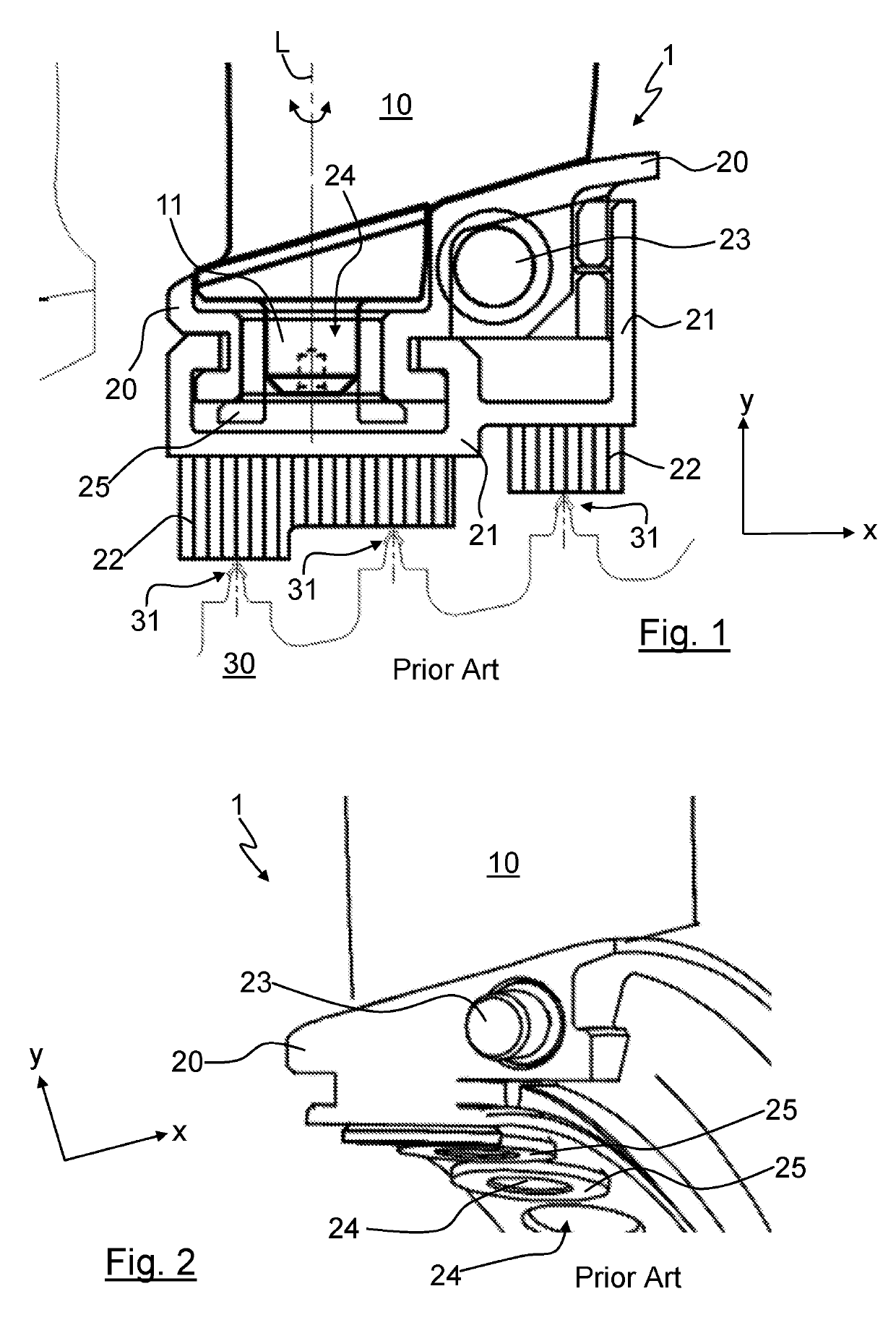
[0060]For better understanding of the invention, FIG. 1 shows a cutout of a generic guide vane assembly 1 of a turbomachine, which is known from prior art and has an inner ring segment 20, in the region of the inner ring segment 20 in a side view.

[0061]The guide vanes 10 are mounted on the inner ring segment 20 in a way that is known from prior art, whereby, to this end, the inner ring segment 20 has guide vane bearing mounts 24, which are arranged uniformly distributed in the peripheral direction and are designed, in particular, as through openings, wherein the guide vanes 10 are joined to the inner ring segment 20 via bearing journals 11 that extend in a radial direction y and are supported at the inner ring segment 20 in a radial direction.

[0062]In this case, the guide vanes 10 are adjustably formed and joined to the inner ring segment 20 so as to rotate around a longitudinal axis L. For minimization of the friction between the bearing journal 11 and the inner ring segment 20, a ...


PUM


Abstract

The invention relates to an inner ring for a guide vane assembly for mounting adjustable guide vanes of a turbomachine, of a compressor stage or turbine stage of a gas turbine, a guide vane assembly for a turbomachine having an inner ring, a turbomachine having an inner ring, and a method for producing an inner ring, wherein the inner ring has a plurality of guide vane bearing mounts, which are each arranged spaced apart in the peripheral direction, recesses, which are each formed for receiving a bearing element, in particular a bearing journal, of a guide vane, wherein, between at least two adjacent guide vane bearing mounts, the inner ring has at least one depression with a wall thickness in a radial direction that is reduced in comparison to a region that abuts the depression and is outside of the depression.

Description

BACKGROUND OF THE INVENTION[0001]The present invention relates to an inner ring for a guide vane assembly for mounting guide vanes, in particular adjustable guide vanes, of a turbomachine, in particular of a compressor stage or turbine stage of a gas turbine, a guide vane assembly, and a turbomachine, in particular a gas turbine having such an inner ring as well as a method for the production thereof.[0002]During the operation of turbomachines having inner rings of this kind, the inner rings are generally subjected to thermal loads, in particular partially fluctuating and / or high temperature gradients, in particular due to the working fluid flowing through the guide vane assembly and thus at least partially flowing around the inner ring, and / or due to sliding seals between the guide vane assembly and a rotor that rotates relative to the guide vane assembly. The thermal load can result in undesired, thermally caused deformations of the inner ring, in particular the widening of gaps a...

Claims


Application Information

Patent Timeline
Patent Type & Authority Applications(United States)
IPC IPC(8): F01D9/04F01D25/16
CPCF05D2240/50F01D9/042F05D2240/12F05D2220/32F01D25/162F05D2250/10F01D11/001F01D17/162
Inventor ALBERS, LOTHAR
Owner MTU AERO ENGINES GMBH
Why Eureka
Try Eureka