Radiographic image detection device

Active Publication Date: 2019-09-12
FUJIFILM CORP
View PDF0 Cites 1 Cited by
  • Summary
  • Abstract
  • Description
  • Claims
  • Application Information

AI Technical Summary

Benefits of technology

The invention provides a radiographic image detection device that can prevent the sensor panel from being heated up by the circuit substrate and improves the quality of the radiographic image. This is achieved by dividing the rear surface into two regions with different mounting density of circuit substrates, and utilizing the high thermal conductivity from the high-density region to the low-density region. The device also has an anisotropic thermal conductivity in at least the rear surface, which further reduces the heating effect on the sensor panel and improves image quality.

Problems solved by technology

Therefore, a temperature distribution in the rear surface of the base is not uniform and the rear surface of the base has a portion that is locally heated and another portion that is not locally heated.
In a case in which heat with a non-uniform temperature distribution is transferred to the sensor panel through the base and the sensor panel is locally heated, local density unevenness occurs in a radiographic image and the quality of the radiographic image is degraded.
However, there are no measures for the degradation of the quality of a radiographic image caused by a non-uniform temperature distribution in the rear surface of the base.

Method used


Image

  • Radiographic image detection device
  • Radiographic image detection device
  • Radiographic image detection device

Examples


first embodiment

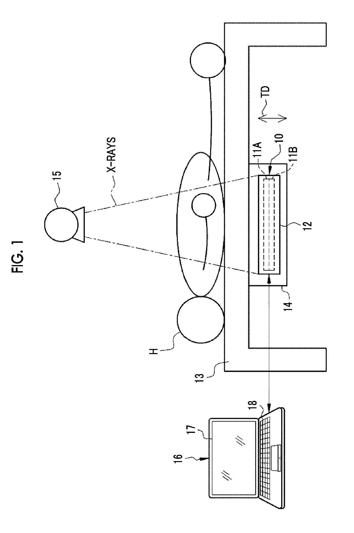
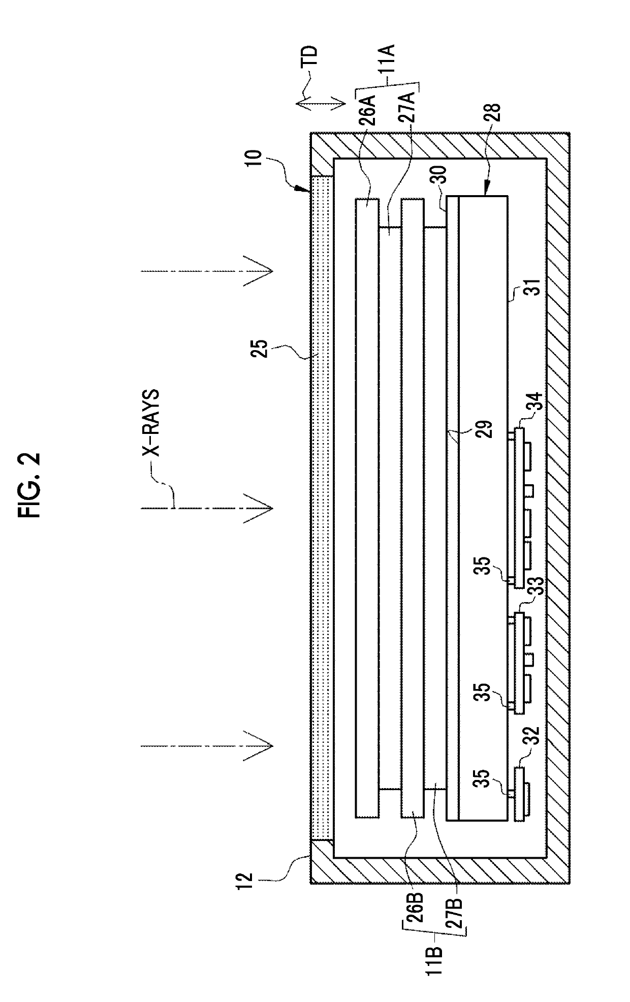
[0028]In FIG. 1, an electronic cassette 10 corresponding to a radiographic image detection device according to the invention has a first sensor panel 11A and a second sensor panel 11B which are accommodated in a housing 12. The first and second sensor panels 11A and 11B are thin plates having a rectangular shape in a plan view and are sequentially arranged in a thickness direction TD.

[0029]The housing 12 is a portable box having a rectangular parallelepiped shape and has a size which is based on the International Organization for Standardization (ISO) 4090:2001 and is substantially equal to the size of, for example, a film cassette, an imaging plate (IP) cassette, or a computed radiography (CR) cassette. The housing 12 is made of a conductive material, such as a resin mixed with carbon fibers, a resin mixed with an aluminum or nickel filler, an aluminum alloy, or a magnesium alloy.

[0030]The electronic cassette 10 is set in a holder 14 of an imaging table 13 on which a subject H lies...

second embodiment

[0075]An electronic cassette 80 according to a second embodiment illustrated in FIG. 6 is the same as the electronic cassette 10 according to the first embodiment illustrated in FIG. 2 in, for example, the configuration of the first and second sensor panels 11A and 11B and the structure in which the first and second sensor panels 11A and 11B are attached to a front surface 82 of a base 81 through the heat insulating member 30. The electronic cassette 80 differs from the electronic cassette 10 in that a sheet 84 is attached to a rear surface 83 of the base 81.

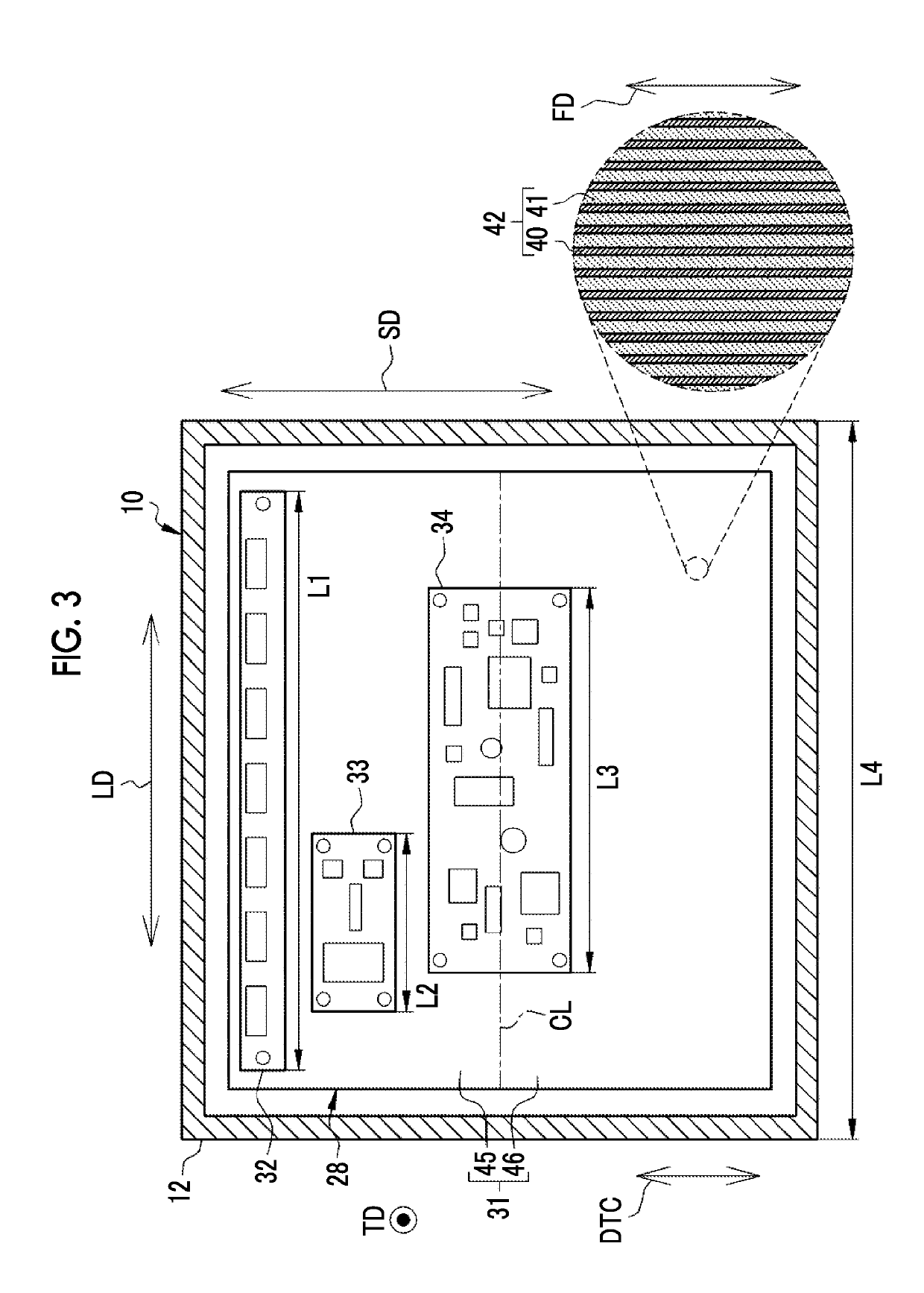
[0076]The base 81 is not made of the same pitch-based carbon fiber reinforced resin as that forming the base 28 according to the first embodiment and is made of, for example, stainless steel. Instead, the sheet 84 is made of a pitch-based carbon fiber reinforced resin obtained by impregnating a pitch-based carbon fiber with a matrix resin, similarly to the base 28 according to the first embodiment. The fiber directions FD of the...


PUM


Abstract

A first sensor panel, a second sensor panel, and a base are accommodated in a housing of an electronic cassette. Circuit substrates are mounted on a rear surface of the base. The base is made of a pitch-based carbon fiber reinforced resin obtained by impregnating a pitch-based carbon fiber with a matrix resin. The fiber directions of the pitch-based carbon fibers are aligned with one direction. Therefore, the base has high thermal conductivity in a direction parallel to the fiber direction. As a result, the driving heat of the circuit substrates is rapidly diffused to the entire rear surface.

Description

CROSS-REFERENCE TO RELATED APPLICATIONS[0001]This application claims priority under 35 U.S.C § 119 (a) to Japanese Patent Application No. 2018-039376 filed on 6 March 2018. The above application is hereby expressly incorporated by reference, in its entirety, into the present application.BACKGROUND OF THE INVENTION1. Field of the Invention[0002]The present invention relates to a radiographic image detection device.2. Description of the Related Art[0003]In a medical field, a diagnosis is made on the basis of a radiographic image detected by a radiographic image detection device. The radiographic image detection device comprises a sensor panel, a circuit unit, and a base. In the sensor panel, a plurality of pixels that accumulate charge in response to radiation which has been emitted from a radiation source and then transmitted through a subject (patient) are two-dimensionally arranged. The radiographic image detection device comprising the sensor panel is also called a flat panel dete...

Claims


Application Information

Patent Timeline
IPC IPC(8): G01T1/24A61B6/00
CPCA61B6/505G01T1/244A61B6/4233G01T1/247A61B6/4283G01T1/202G01T1/161A61B6/4208G01T7/00G03B42/02
Inventor TATEISHI, MASATERU
Owner FUJIFILM CORP
Why Eureka
Try Eureka