Multilayer capacitor

Active Publication Date: 2019-09-12
SAMSUNG ELECTRO MECHANICS CO LTD
View PDF12 Cites 0 Cited by
  • Summary
  • Abstract
  • Description
  • Claims
  • Application Information

AI Technical Summary

Benefits of technology

The patent text describes how to make an electronic component that reduces the noise in the sound of low-frequency sounds and the vibrations in the sounds of high-frequency sounds. This can be useful for improving the quality of audio components in devices such as earphones or headphones.

Problems solved by technology

When a period of the applied voltage is within an audio frequency band, the displacement of the dielectric material by the piezoelectric effect gives rise to vibrations that are transferred to a board through solders, and the vibrations of the board are heard as sound.
This is known as acoustic noise and is considered to be problematic in the electronic device.
When a device is operated in a silent environment, a user may detect acoustic noise as a strange sound and may believe that a fault has occurred in the device.
Additionally, in a device having an audio circuit, the acoustic noise may overlap audio output such that device audio / sound quality may be deteriorated.
In addition, when piezoelectric vibrations of the multilayer capacitor are generated in a high frequency region of 20 kHz or more, the vibrations may give rise to malfunctions of various sensors used in the information technology (IT) and industry / electrical component fields separately from any acoustic noise recognized by the ears of a person.

Method used


Image

  • Multilayer capacitor
  • Multilayer capacitor
  • Multilayer capacitor

Examples


Embodiment Construction

[0028]Hereinafter, exemplary embodiments of the present disclosure will now be described in detail with reference to the accompanying drawings.

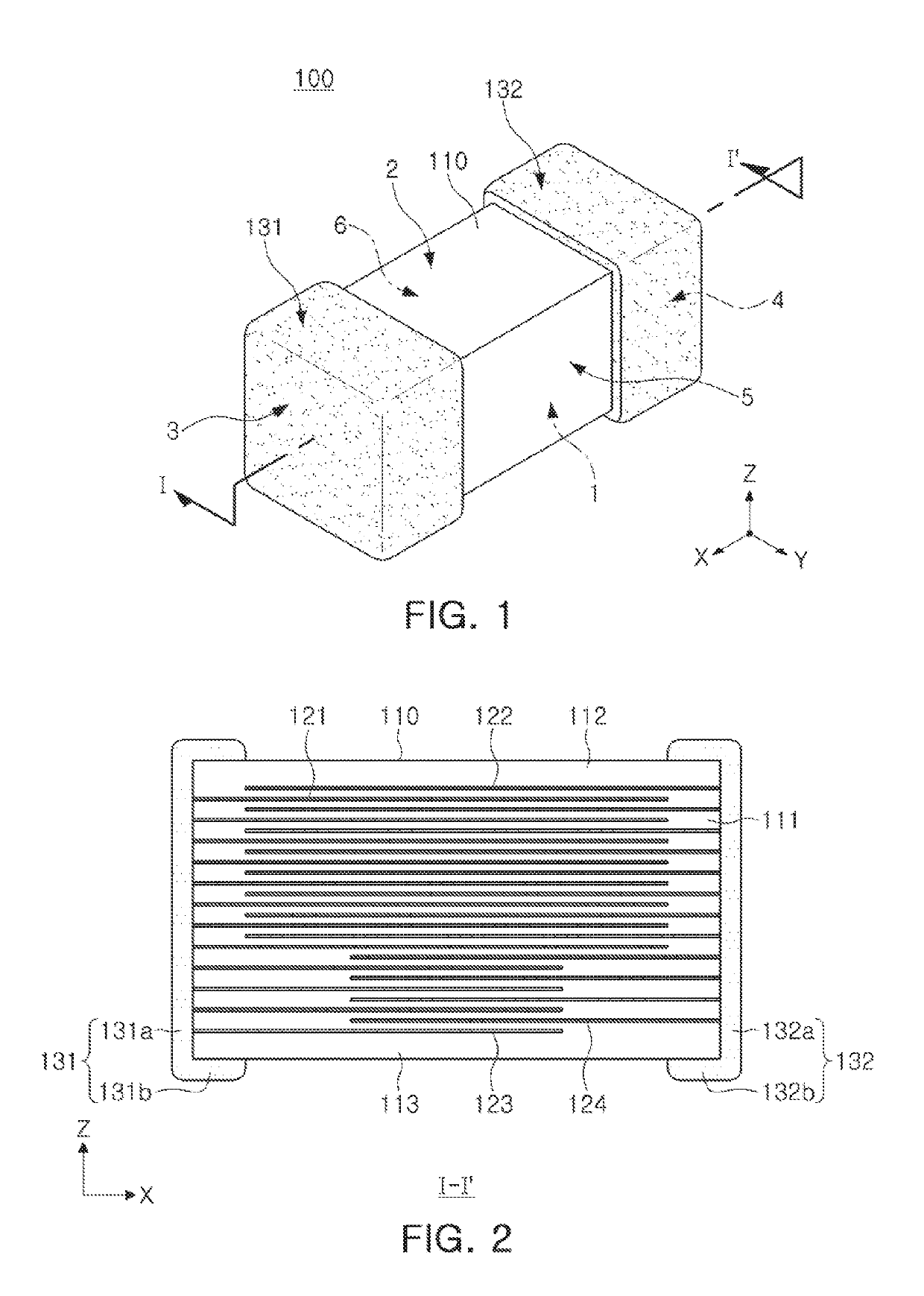
[0029]Hereinafter, directions of a capacitor body 110 will be defined in order to clearly describe exemplary embodiments in the present disclosure. The X, Y and Z directions shown in the drawings refer to a length direction, a width direction, and a thickness direction of the capacitor body 110, respectively. In addition, in the present exemplary embodiment, the Z direction refers to a stacking direction in which dielectric layers are stacked in a capacitor body.

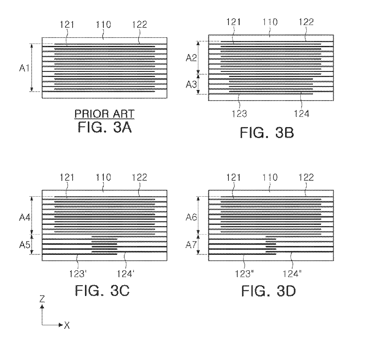
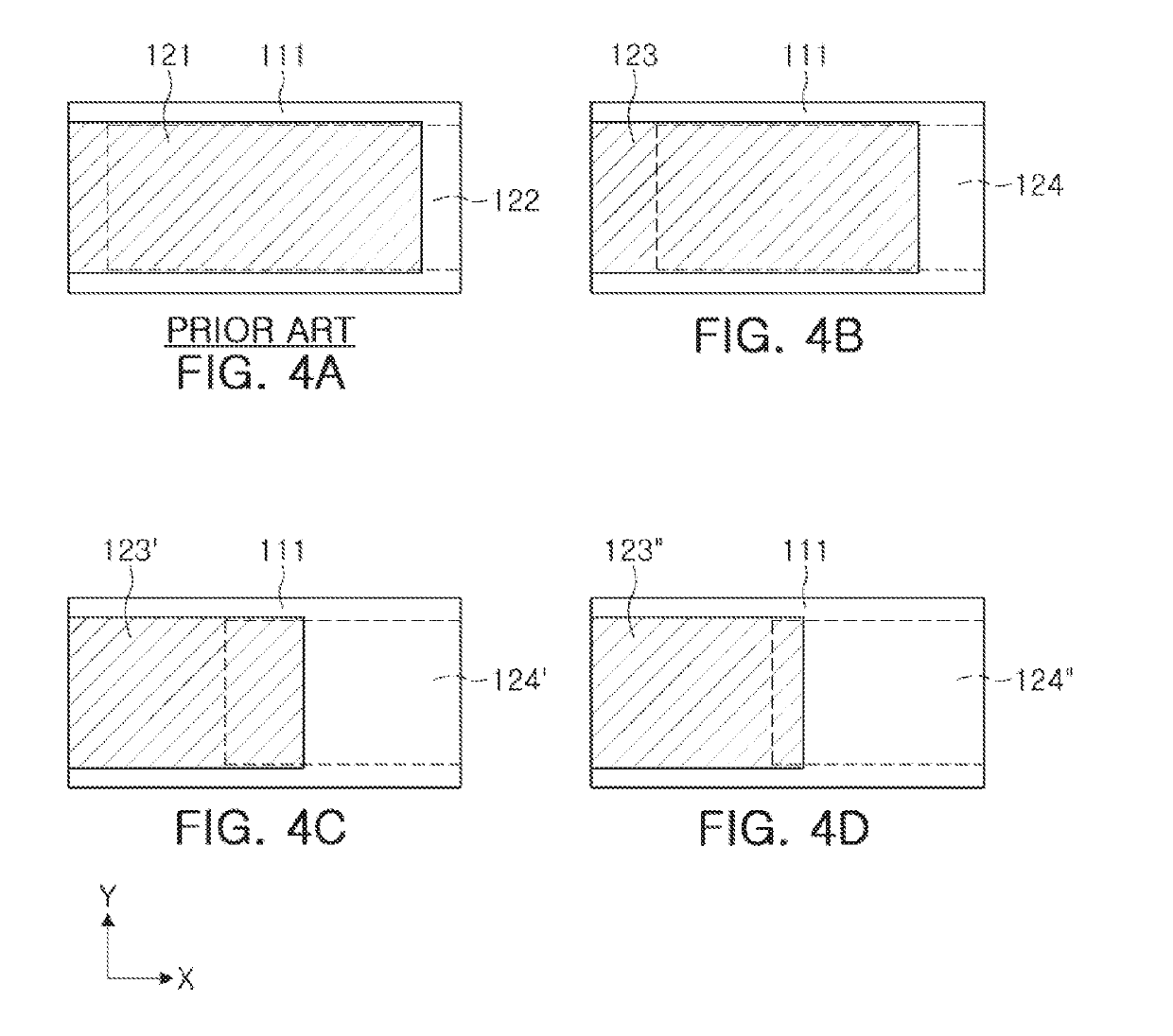
[0030]Referring to FIGS. 1, 2, 3B, 4B, 5B, and 5F, a multilayer capacitor according to an exemplary embodiment in the present disclosure may include a capacitor body 110 and first and second external electrodes 131 and 132 formed on opposite end surfaces of the capacitor body 110.

[0031]The capacitor body 110 may be formed by stacking and then sintering a plurality of dielectric layers...


PUM

PropertyMeasurementUnit
Fractionaaaaaaaaaa
Fractionaaaaaaaaaa
Fractionaaaaaaaaaa

Abstract

A multilayer capacitor in which acoustic noise is reduced has an area of overlap between internal electrodes in an active region of a lower portion of a capacitor body that is smaller than an area of overlap between internal electrodes in an active region of an upper portion of the capacitor body. The multilayer capacitor can be bonded to a board by relatively small solders such that the lower portion is adjacent the board. Deviations between areas of overlap of adjacent internal electrodes in the upper and lower portions of the active region are minimized to reduce piezoelectric deformation of the capacitor body.

Description

CROSS-REFERENCE TO RELATED APPLICATION(S)[0001]This application claims benefit of priority to Korean Patent Applications No. 10-2018-0028253 filed on Mar. 9, 2018 and No. 10-2018-0064146 filed on Jun. 4, 2018 in the Korean Intellectual Property Office, the disclosures of which are incorporated herein by reference in their entireties.BACKGROUND1. Field[0002]The present disclosure relates to a multilayer capacitor.2. Description of Related Art[0003]Recently, efforts have been made in the development of electronic devices to reduce noise produced by electronic components, such that acoustic noise generated by multilayer capacitors (MLCCs).[0004]Dielectric materials used in multilayer capacitors have piezoelectric characteristics, and may thus be deformed in synchronization with an applied voltage.[0005]When a period of the applied voltage is within an audio frequency band, the displacement of the dielectric material by the piezoelectric effect gives rise to vibrations that are transfer...

Claims


Application Information

Patent Timeline
IPC IPC(8): H01G4/35H01G4/12H01G4/30H01G4/232H01G4/01
CPCH01G4/1227H01G4/232H01G4/30H01G4/01H01G4/35H01G4/012H01G4/005H01G4/12
Inventor SIM, WON CHULAHN, YOUNG GHYUPARK, HEUNG KILSON, SOO HWAN
Owner SAMSUNG ELECTRO MECHANICS CO LTD
Why Eureka
Try Eureka