Liquid Discharge Head

Active Publication Date: 2019-09-19
BROTHER KOGYO KK
View PDF0 Cites 3 Cited by
  • Summary
  • Abstract
  • Description
  • Claims
  • Application Information

AI Technical Summary

Benefits of technology

[0008]According to the above configuration, the discharge common channel has an expansion portion wider than the first discharge portion. By virtue of this, because the discharge common channel is expanded, it is possible to lessen the resistance against the liquid flow in the discharge common channel and, furthermore, it is possible to reduce the resistance difference between the respective pressure chambers. By virtue of this, it is possible to lessen the difference

Problems solved by technology

However, because the liquid is in contact with the ambient air via the nozzles even during the time of not being jetted, there is an increase in viscosity of the liquid in the vicinity of the nozzles.
On this occasion, when there is a large resistance (against the liquid flow) in the circulation channel, then the liquid differs in flow speed between the downstream side and the upstream side in the circulation channel Hence, a difference in the flow speed of the liquid a

Method used


Image

  • Liquid Discharge Head
  • Liquid Discharge Head
  • Liquid Discharge Head

Examples


first embodiment

Liquid Discharge Apparatus

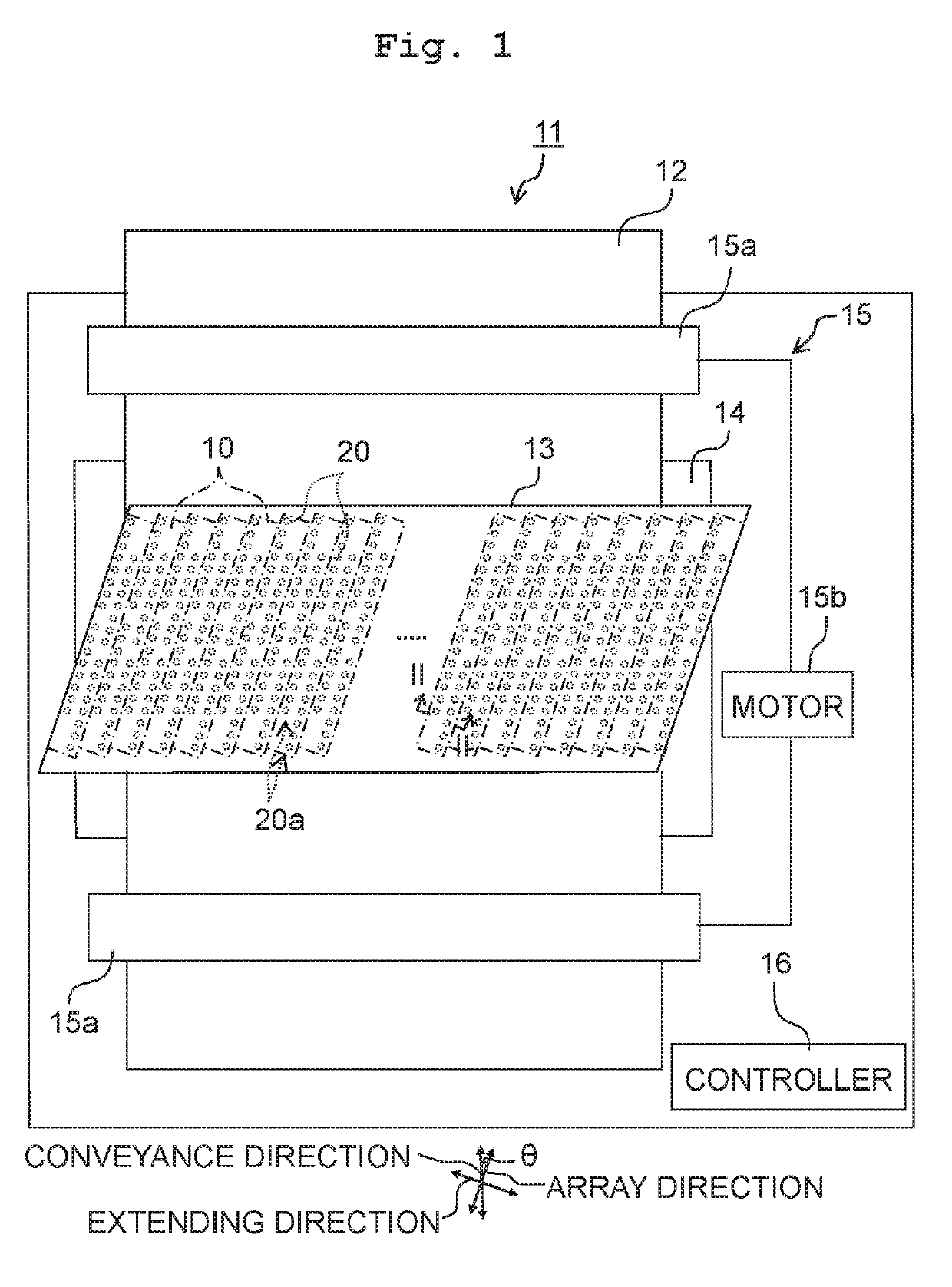
[0020]A liquid discharge apparatus 11 using heads 10 according to a first embodiment of the present disclosure is, as depicted in FIG. 1 for example, a printer carrying out printing on recording medium 12 with the liquid by way of jetting the liquid such as ink or the like while conveying the recording medium 12 such as printing paper or the like. Note that although the liquid discharge apparatus 11 will be explained below as an apparatus using the heads 10, apparatuses using the heads 10 are not limited to the above. Further, as the liquid discharge apparatus 11, a printer will be explained below, but the liquid discharge apparatus 11 is not limited to a printer as far as it is an apparatus that discharges liquid.

[0021]The liquid discharge apparatus 11 includes a head unit 13, a platen 14, a conveyance mechanism 15, and a controller 16. The head unit 13 has the plurality of heads 10, and the plurality of heads 10 are arranged to align in a direction orthog...

first modified embodiment

[0075]In a head 110 according to a first modified embodiment based on the first embodiment, as depicted in FIG. 4A, an expansion portion 134 of a second discharge portion 132 of a discharge common channel 130 has an angular portion 134c whose cross-sectional shape orthogonal to the array direction is curved. For example, the expansion portion 134 may have the angular portion 134c curved between a surface 134a intersecting the width direction and surfaces 134b intersecting the stacking direction.

[0076]For example, the expansion portion 134 is enclosed circumferentially in the communication plate 52 by a surface (the upper surface 134a) intersecting the stacking direction (being orthogonal thereto for example), a pair of surfaces (the lateral surfaces 134b) intersecting the width direction (being orthogonal thereto for example), and a pair of surfaces (the end surfaces) intersecting the array direction (being orthogonal thereto for example). The angular portion 134c between the upper ...

second modified embodiment

[0077]In a head 210 according to a second modified embodiment based on the first embodiment, as depicted in FIG. 4B, an expansion portion 234 of a second discharge portion 232 of a discharge common channel 230 has an angular portion 234c whose cross-sectional shape orthogonal to the array direction is inclined. For example, the expansion portion 234 may have the angular portion 234c inclined between a surface 234a intersecting the width direction and surfaces 234b intersecting the stacking direction.

[0078]For example, the expansion portion 234 is enclosed circumferentially in the communication plate 52 by an upper surface 234a, a pair of lateral surfaces 234b, and a pair of end surfaces. The angular portion 234c between the upper surface 234a and the lateral surfaces 234b is formed by an inclined surface chamfered into an oblique line inclined with respect to the upper surface 234a and the lateral surfaces 234b at a cross section along the array direction. Because the liquid smoothl...


PUM


Abstract

There is provided a liquid discharge head including: a communication plate formed with a descender connected to a nozzle, a pressure chamber plate including a plurality of pressure chambers aligning in an array direction, a piezoelectric element, and a discharge common channel. The discharge common channel extends in the array direction, is connected to the plurality of pressure chambers, and has a first discharge portion and a second discharge portion. The discharge common channel is configured to discharge liquid toward one side in the array direction. The second discharge portion includes an expansion portion to expand beyond the first discharge portion in a width direction orthogonal to the stacking direction and to the array direction.

Description

CROSS REFERENCE TO RELATED APPLICATION[0001]The present application claims priority from Japanese Patent Application No. 2018-050002 filed on Mar. 16, 2018, the disclosure of which is incorporated herein by reference in its entirety.BACKGROUNDField of the Invention[0002]The present disclosure relates to a liquid discharge head such as, for example, the head of a liquid discharge apparatus.Description of the Related Art[0003]As an apparatus having a conventional liquid discharge head, there are known, for example, liquid discharge apparatuses. Such a publicly known liquid discharge apparatus has stacked communication plate provided with communication channels in communication with nozzles, and a channel-forming substrate provided with pressure generation chambers in communication with the communication channels. A circulation channel is provided in the communication plate and the channel-forming substrate, and the circulation channel is in communication with the pressure generation c...

Claims


Application Information

Patent Timeline
IPC IPC(8): B41J2/14B41J2/045
CPCB41J2002/14362B41J2002/14467B41J2/045B41J2202/12B41J2/14201B41J2/155B41J2002/14419B41J2/14233B41J2002/14241B41J2202/11B41J2002/14491
Inventor KATO, YASUO
Owner BROTHER KOGYO KK
Why Eureka
Try Eureka