Vertical antenna patch in cavity region

a vertical antenna and cavity region technology, applied in the field of antenna devices, can solve the problem that the size of the antenna must be sufficiently small to match the wavelength, and achieve the effect of reducing the propagation of surface waves

Active Publication Date: 2019-09-19
SONY MOBILE COMM INC
View PDF0 Cites 10 Cited by
  • Summary
  • Abstract
  • Description
  • Claims
  • Application Information

AI Technical Summary

Benefits of technology

[0005]According to an embodiment, a device is provided. The device comprises a multi-layer circuit structure having multiple layers stacked along a vertical direction. Further, the device comprises at least one cavity region formed at an edge of the multi-layer circuit structure. The at least one cavity region is formed of multiple non-conductive vias from which a dielectric substrate material of the multi-layer circuit structure is removed. Further, the device comprises at least one vertical antenna patch arranged in the at least one cavity region. This is in particular beneficial in the case of substrate materials having a high dielectric constant, such as ceramic based materials. In some scenarios, the dielectric constant of the substrate material may be more than 3, e.g., in the range of 3 to 20, typically in the range of 5 to 8. By the cavity region, adverse influences of the substrate material on the transmission characteristics of the antenna patch, e.g., by attenuating or distorting radio signals, can be avoided. Further, the cavity region may allow for reducing propagation of surface waves along the edge of the multi-layer circuit structure.

Problems solved by technology

However, an issue which arises with the utilization of such high frequencies is that antenna sizes need to be sufficiently small to match the wavelength.

Method used


Image

  • Vertical antenna patch in cavity region
  • Vertical antenna patch in cavity region
  • Vertical antenna patch in cavity region

Examples


Embodiment Construction

[0042]In the following, exemplary embodiments of the invention will be described in more detail. It has to be understood that the following description is given only for the purpose of illustrating the principles of the invention and is not to be taken in a limiting sense. Rather, the scope of the invention is defined only by the appended claims and is not intended to be limited by the exemplary embodiments described hereinafter.

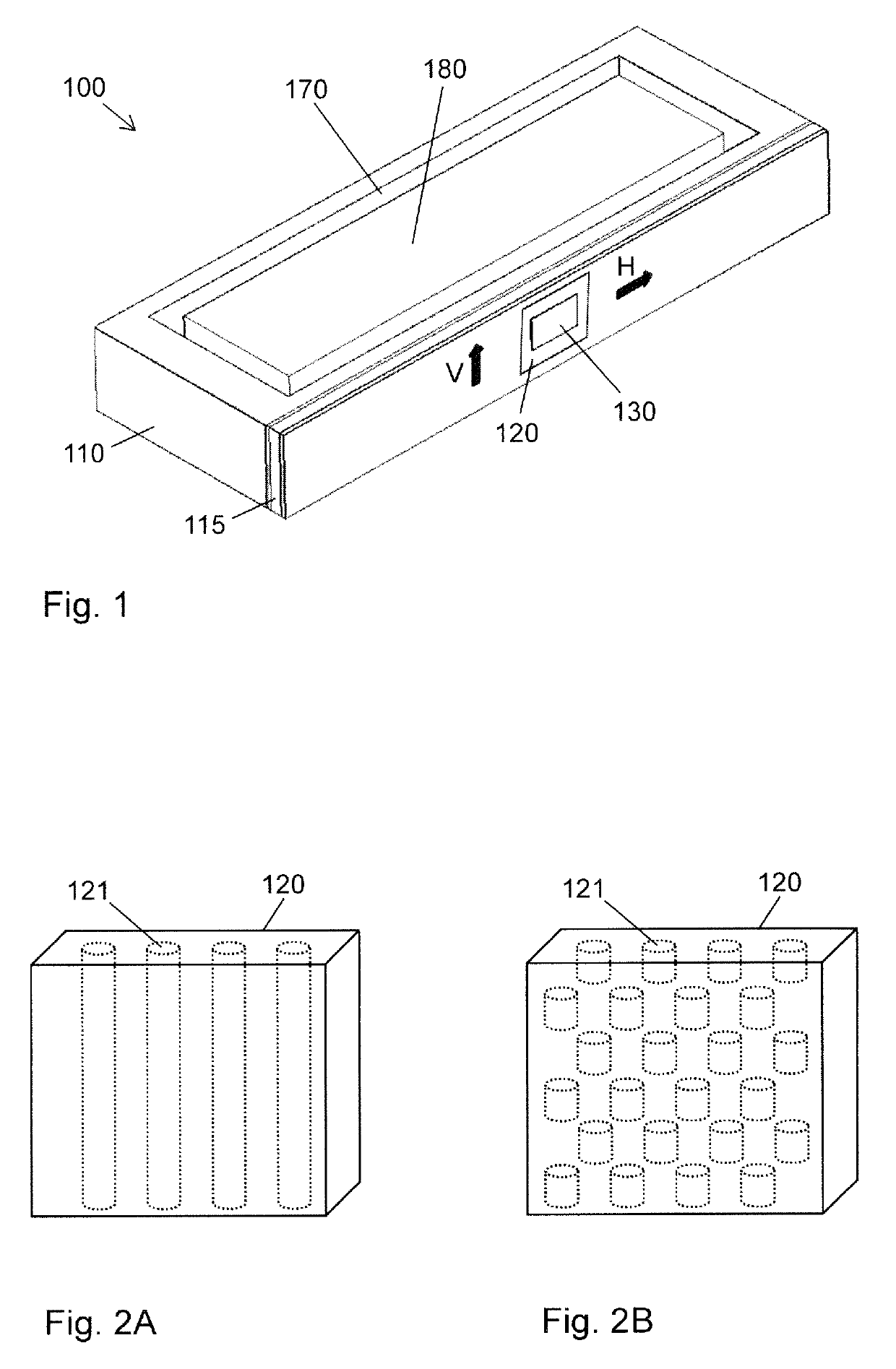
[0043]The illustrated embodiments relate to antennas for transmission of radio signals, in particular of short wavelength radio signals in the cm / mm wavelength range. The illustrated antennas and antenna devices may for example be utilized in communication devices, such as a mobile phone, smartphone, tablet computer, or the like.

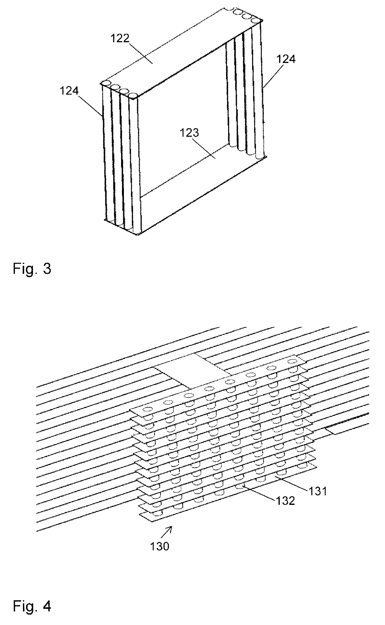
[0044]In the illustrated concepts, a multi-layer circuit structure is utilized for forming a patch antenna. The multi-layer circuit structure has multiple layers stacked in a vertical direction. The layers of the multi-layer circuit ...


PUM


Abstract

A multi-layer circuit structure (110) has multiple layers stacked along a vertical direction. Further, at least one cavity region (120) is formed at an edge of the multi-layer circuit structure (110). The at least one cavity region (120) is formed of multiple non-conductive vias from which a dielectric substrate material of the multi-layer circuit structure (120) is removed. Further, the device comprises at least one vertical antenna patch (130) arranged in the at least one cavity region (120).

Description

FIELD OF THE INVENTION[0001]The present invention relates to antenna devices and to communication devices equipped with one or more of such antenna devices.BACKGROUND OF THE INVENTION[0002]In wireless communication technologies, various frequency bands are utilized for conveying communication signals. In order to meet increasing bandwidth demands, also frequency bands in the millimeter wavelength range, corresponding to frequencies in the range of about 10 GHz to about 100 GHz, are considered. For example, frequency bands in the millimeter wavelength range are considered as candidates for 5G (5th Generation) cellular radio technologies. However, an issue which arises with the utilization of such high frequencies is that antenna sizes need to be sufficiently small to match the wavelength. Further, in order to achieve sufficient performance, multiple antennas (e.g., in the form of an antenna array) may be needed in small sized communication devices, such as mobile phones, smartphones,...

Claims


Application Information

Patent Timeline
Patent Type & Authority Applications(United States)
IPC IPC(8): H01Q1/24H01Q9/04H01Q1/38
CPCH01Q9/0457H01Q1/243H01Q9/0414H01Q1/38H01Q9/0407H01Q15/10H01Q19/06H01Q21/0093H01Q21/067H01Q21/08H01Q25/001
Inventor YING, ZHINONGZHAO, KUN
Owner SONY MOBILE COMM INC
Why Eureka
Try Eureka