Spatial reuse in WLAN multi-ap network

a multi-ap network and spatial reuse technology, applied in the field of wifi network communication, can solve the problems of overlapping coverage regions subject to transmission interference, unable to use the full bandwidth of an ap, and the repeater is usually only limited, so as to improve the overall throughput of the network and efficiently use the resource units

Active Publication Date: 2019-09-19
MEDIATEK SINGAPORE PTE LTD SINGAPORE
View PDF0 Cites 9 Cited by
  • Summary
  • Abstract
  • Description
  • Claims
  • Application Information

AI Technical Summary

Benefits of technology

[0005]Embodiments of the present disclosure provide a spatial reuse mechanism that enables a repeater network to efficiently use the resource units of a wireless local area network (WLAN) while avoiding interference among the coordinating devices (e.g., repeaters) in Orthogonal Frequency-Division Multiple Access (OFDMA) transmissions, thereby enhancing overall throughput of the network.
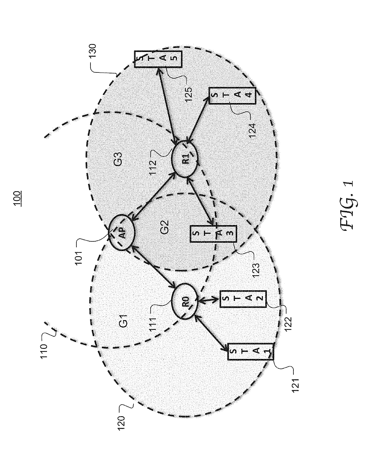
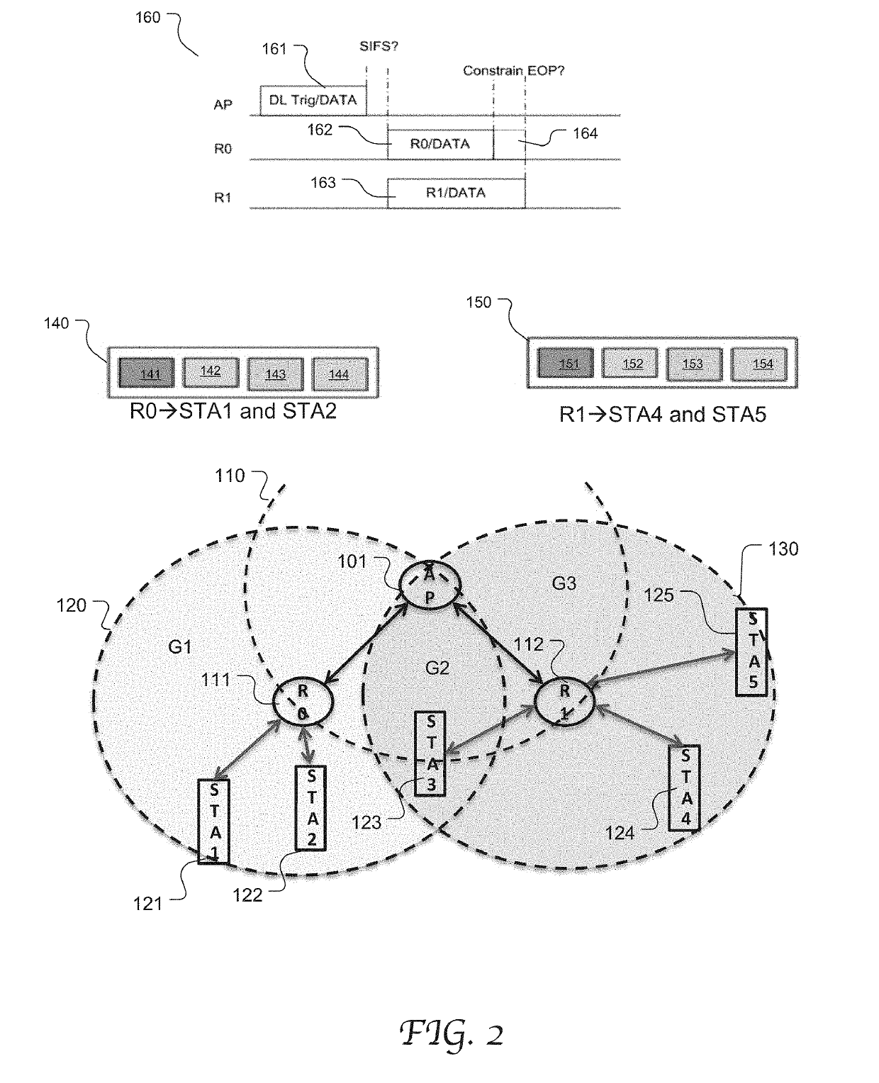
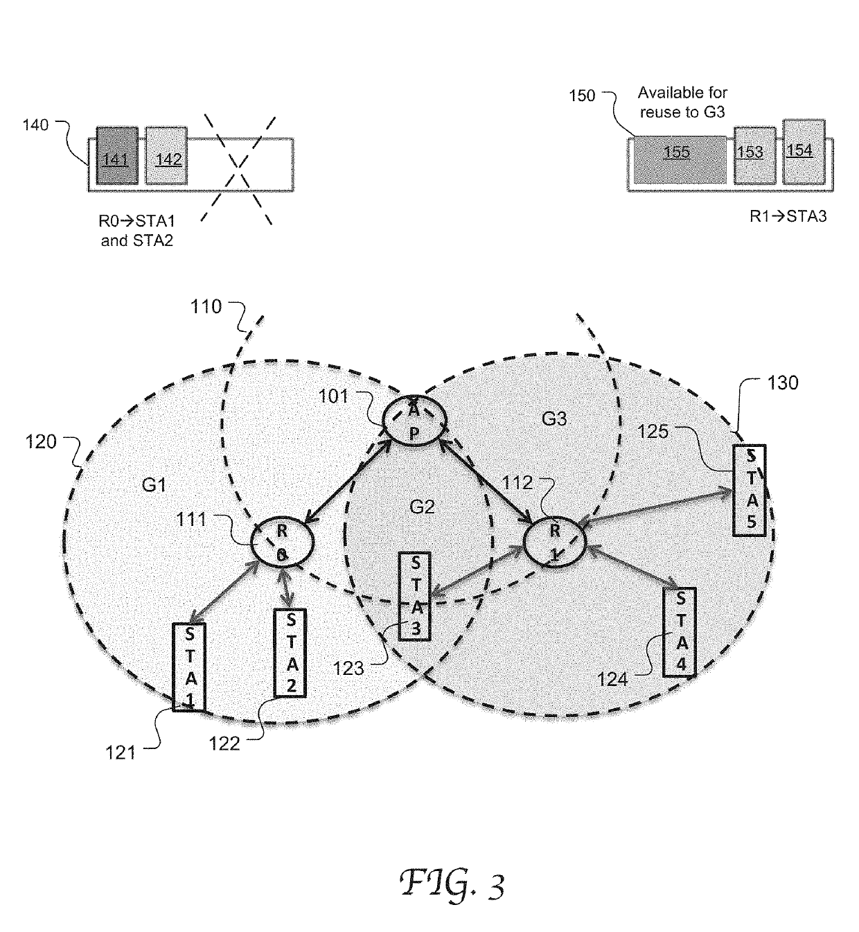
[0010]According to embodiments of the present disclosure, the non-AP STAs are grouped based on their connectivity with the individual repeaters and the coverage regions of the repeaters. Based on the grouping, certain RUs can be reused for multiple groups without causing interference, thereby expanding the bandwidth of these groups. In this manner, the frequency resources of the WLAN can be used efficiently and the network throughput can be advantageously and significantly increased.

Problems solved by technology

In a densely deployed WLAN environment, it is common to have multiple repeaters located in a close range and simultaneous transmission to and from the repeaters may cause interference due to the overlapping coverage regions.
Thus, a repeater is usually only limited to using the allocated RUs for relay transmissions with the non-AP STAs and cannot use the full bandwidth that an AP provides.
Similarly, neighboring APs with overlapping coverage region would be subject to transmission interference in the overlapping region.

Method used


Image

  • Spatial reuse in WLAN multi-ap network
  • Spatial reuse in WLAN multi-ap network
  • Spatial reuse in WLAN multi-ap network

Examples


Embodiment Construction

[0023]Reference will now be made in detail to the preferred embodiments of the present invention, examples of which are illustrated in the accompanying drawings. While the invention will be described in conjunction with the preferred embodiments, it will be understood that they are not intended to limit the invention to these embodiments. On the contrary, the invention is intended to cover alternatives, modifications, and equivalents which may be included within the spirit and scope of the invention as defined by the appended claims. Furthermore, in the following detailed description of embodiments of the present invention, numerous specific details are set forth in order to provide a thorough understanding of the present invention. However, it will be recognized by one of ordinary skill in the art that the present invention may be practiced without these specific details. In other instances, well-known methods, procedures, components, and circuits have not been described in detail ...


PUM


Abstract

Systems and methods of WLAN communication including efficient spatial reuse mechanisms for relay transmissions between a repeater network and non-AP STAs in OFDMA. The non-AP STAs are grouped based on their connectivity with the individual repeaters and the radio coverage regions of the repeaters. Each group is either a non-overlapping group with the constituent non-AP STAs located in a non-overlapping coverage region of a particular repeater, or an overlapping group with the constituent non-AP STAs located in an overlapping coverage region of two or more repeaters. Based on the grouping, certain RUs (or subchannels) are reused for multiple groups without causing inter-group interference, thereby expanding the bandwidths used in the relay operations. RU allocation based on grouping can be used in combination with transmit power adjustment to achieve efficient spatial reuse in OFDMA.

Description

CROSSREFERENCE TO RELATED APPLICATION[0001]This patent application claims priority and benefit of U.S. Provisional Patent Application No. 62 / 644,631, entitled “flax REPEATER AND SPATIAL REUSE OPERATION,” filed on Mar. 19, 2018, the entire content of which is herein incorporated by reference for all purposes.TECHNICAL FIELD[0002]Embodiments of the present disclosure relate generally to the field of Wi-Fi network communication, and more specifically, to the field Wi-Fi repeater network communication mechanisms.BACKGROUND OF THE INVENTION[0003]In a wireless local area network (WLAN), one or more repeater access points (or “repeaters” herein) can be placed within radio range of an access point (APs) connected to the wired LAN to extend the range of an infrastructure or to overcome an obstacle that blocks radio communication. A repeater, also known as a booster or an extender, is capable of relaying both uplink (UL) and downlink (DL) traffic between the wireless user devices (or non-AP S...

Claims


Application Information

Patent Timeline
Patent Type & Authority Applications(United States)
IPC IPC(8): H04B7/14H04B7/0452H04L27/26H04W16/12H04W52/24
CPCH04L27/2626H04B7/0452H04B7/14H04W52/24H04W84/12H04W16/12H04W16/14H04W72/0453H04W72/541H04J11/0059H04L5/0035H04J11/0056H04L27/2601H04B7/2606H04W52/46H04W52/40H04B7/026
Inventor WANG, JAMES JUNE-MINGPARE, JR., THOMAS EDWARDSEOK, YONGHOBAJKO, GABORLIU, JIANHANWU, TIANYU
Owner MEDIATEK SINGAPORE PTE LTD SINGAPORE
Why Eureka
Try Eureka