Optical transmission system, PON system, and transmission method

a transmission system and optical transmission technology, applied in the field of optical transmission systems, pon systems, and transmission methods, can solve the problems of increasing operational costs, difficulty in using this method with access lines that are required to have a lower cost, and increasing operational costs, so as to avoid the influence of wavelength dispersion and simple configuration

Active Publication Date: 2019-09-19
KDDI CORP
View PDF0 Cites 41 Cited by
  • Summary
  • Abstract
  • Description
  • Claims
  • Application Information

AI Technical Summary

Benefits of technology

[0009]According to the present invention, it is possible to avoid the influence of wavelength dispersion using a simple configuration.
[0010]Other characteristics and advantages of the present invention will become clear th

Problems solved by technology

Compensation for wavelength dispersion needs to be performed optically, but in the case of using a method in which a dispersion compensation fiber that depends on the distance of the optical fiber is physically inserted, an increase in operational cost is incurred.
Also, i

Method used


Image

  • Optical transmission system, PON system, and transmission method
  • Optical transmission system, PON system, and transmission method
  • Optical transmission system, PON system, and transmission method

Examples


second embodiment

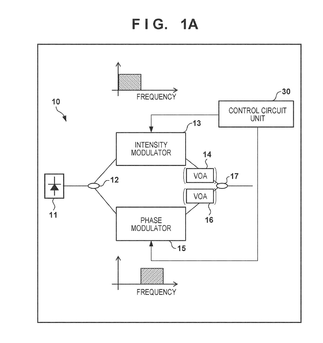
[0034]FIG. 5 is a diagram showing an overall configuration of an optical transmitter according to a second embodiment. The optical transmitter 40 is provided in a transmitting station in the optical transmission system or an OLT in a PON system and includes at least: a semiconductor laser 11, which is a light source that outputs light; a polarization beam splitter (PBS) 18; an intensity modulator 13; a phase modulator 15; a polarization beam combiner (PBC) 19; and a control circuit unit 30.

[0035]The polarization beam splitter 18 performs polarization separation of a received signal, and dividing the received signal into a first continuous light and a second continuous light whose polarization planes are orthogonal to each other. The intensity modulator 13 performs intensity modulation on the first continuous light. The phase modulator 15 performs phase modulation on the second continuous light. The polarization beam combiner 19 performs processing for multiplexing polarized waves th...

third embodiment

[0036]FIG. 6 is a diagram showing an overall configuration of an optical transmitter according to a third embodiment. The optical transmitter 50 is provided in a transmitting station in an optical transmission system or an OLT in a PON system, and as shown in FIG. 6, the intensity modulator 13 and the phase modulator 15 are arranged in series. The method for allocating the channels is the same as that of the first embodiment and the second embodiment, but arranging the intensity modulator 13 and the phase modulator 15 in series eliminates the need for optical devices such as a coupler, a PBS, and a PBC, and thus cost can be suppressed.

fourth embodiment

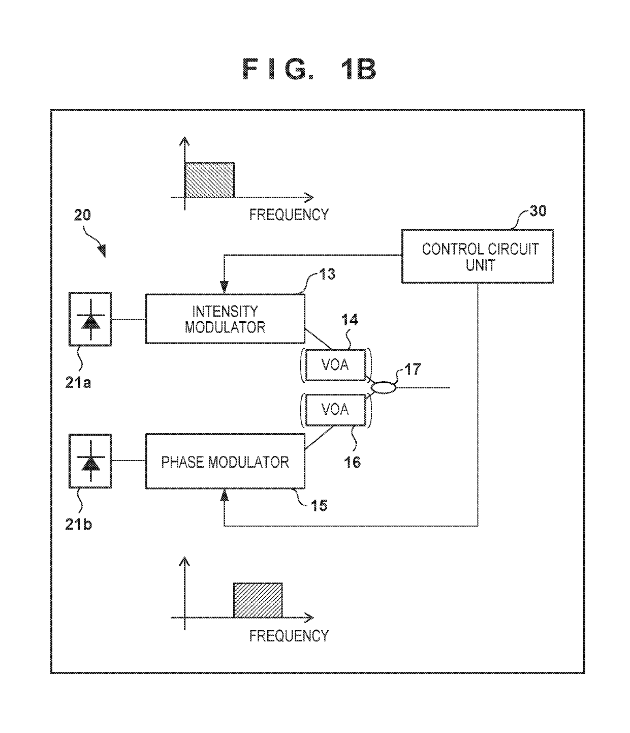
[0037]FIG. 7 is a diagram showing an overall configuration of an optical transmitter according to a fourth embodiment. As shown in FIG. 7, the optical transmitter 60 is provided in a transmitting station in an optical transmission system or an OLT in a PON system, and uses a direct modulation laser 23 in which a semiconductor laser and an intensity modulator are integrated. By using the direct modulation laser 23 in this manner, it is possible to further suppress the cost.


PUM


Abstract

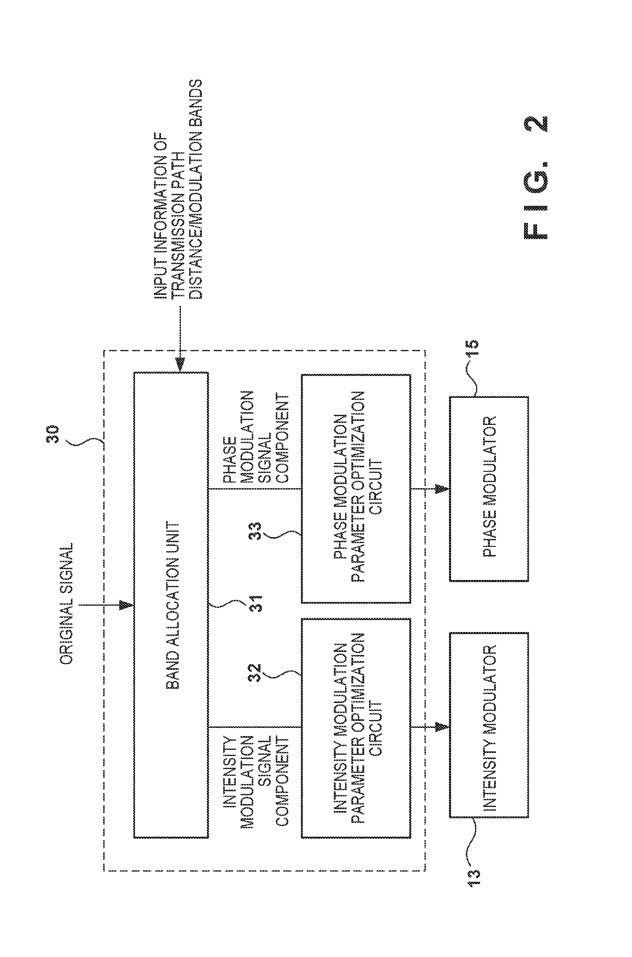
An optical transmission system in which a transmitting station and a plurality of receiving stations are connected via an optical splitter, wherein the transmitting station includes: a controller configured to determine whether to perform intensity modulation or phase modulation on optical signals based on information on transmission distances to the receiving stations and modulation bands; an intensity modulator configured to perform intensity modulation on an optical signal; and a phase modulator configured to perform phase modulation on an optical signal, and wherein one of an intensity modulation signal and a phase modulation signal is transmitted from the transmitting station to each of the receiving stations.

Description

CROSS-REFERENCE TO RELATED APPLICATIONS[0001]This application is a continuation of International Patent Application No. PCT / JP2017 / 045658 filed on Dec. 20, 2017, which claims priority to and the benefit of Japanese Patent Application No. 2017-002200 filed on Jan. 10, 2017, the entire disclosures of which are incorporated herein by reference.TECHNICAL FIELD[0002]The present invention relates to an optical transmission system, a PON system, and a transmission method, including a wavelength dispersion compensation function for multi-carrier transmission, or according to which it is possible to avoid the influence of wavelength dispersion.BACKGROUND ART[0003]In optical fiber transmission, wavelength dispersion is one main factor that causes signal degradation. Compensation for wavelength dispersion needs to be performed optically, but in the case of using a method in which a dispersion compensation fiber that depends on the distance of the optical fiber is physically inserted, an increa...

Claims


Application Information

Patent Timeline
IPC IPC(8): H04B10/54H04B10/548H04B10/2513H04B10/272H04J14/00H04J14/02
CPCH04J14/005H04J14/023H04B10/548H04B10/54H04B10/2513H04J14/0245H04B10/272H04B10/516H04J14/0298
Inventor ISHIMURA, SHOTATANAKA, KAZUKINISHIMURA, KOSUKESUZUKI, MASATOSHI
Owner KDDI CORP
Why Eureka
Try Eureka