
System, method and apparatus for retinal absorption phase and dark field imaging with oblique illumination

a technology of dark field imaging and retinal absorption, which is applied in the field of system, method and apparatus for retinal absorption phase and dark field imaging with oblique illumination, can solve the problems of not directly applicable methods to living biological media, and none of the techniques described above provide phase image information in either quantitative or non-quantitative manner of the inside of the eye without the use of scanning systems

Active Publication Date: 2019-09-26
ECOLE POLYTECHNIQUE FEDERALE DE LAUSANNE (EPFL)
View PDF0 Cites 8 Cited by
  • Summary
  • Abstract
  • Description
  • Claims
  • Application Information

AI Technical Summary

Benefits of technology

The present invention provides a method and system for imaging the tissue of an eye using oblique illumination. The system includes a light delivering device with independently controllable light emitting areas that direct light towards the retina or iris of the eye. The light emitting areas can be in contact with the eye or in contact with the skin surrounding it. The system can capture the output beam of light backscattered from the eye and provide a sequence of images. The captured images can include a quantitative phase and absorption image, a qualitative phase and absorption image, a dark field image, and other image types. The imaging system also have a scanning system and a detector. The technical effect of the invention is to enable improved imaging of the tissue of the eye with improved clarity and accuracy.

Problems solved by technology

Such a method is not directly applicable to living biological media, since transmission illumination is, in general, not possible.
However, none of the techniques described above provide phase image information in either a quantitative or non-quantitative manner of the inside of eye without the use of a scanning system.
Also, as discussed above, this presents several drawbacks and complications, and novel and substantially improved methods, systems, and devices for ophthalmology are desired.

Method used


Image

  • System, method and apparatus for retinal absorption phase and dark field imaging with oblique illumination
  • System, method and apparatus for retinal absorption phase and dark field imaging with oblique illumination
  • System, method and apparatus for retinal absorption phase and dark field imaging with oblique illumination

Examples


first embodiment

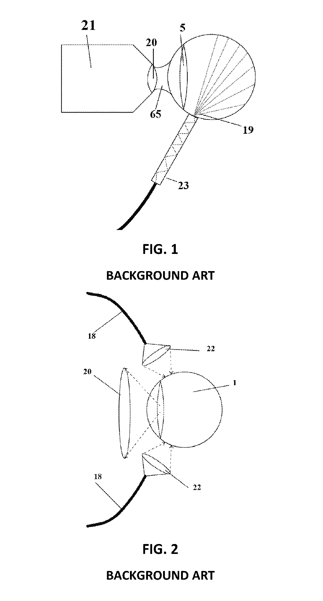
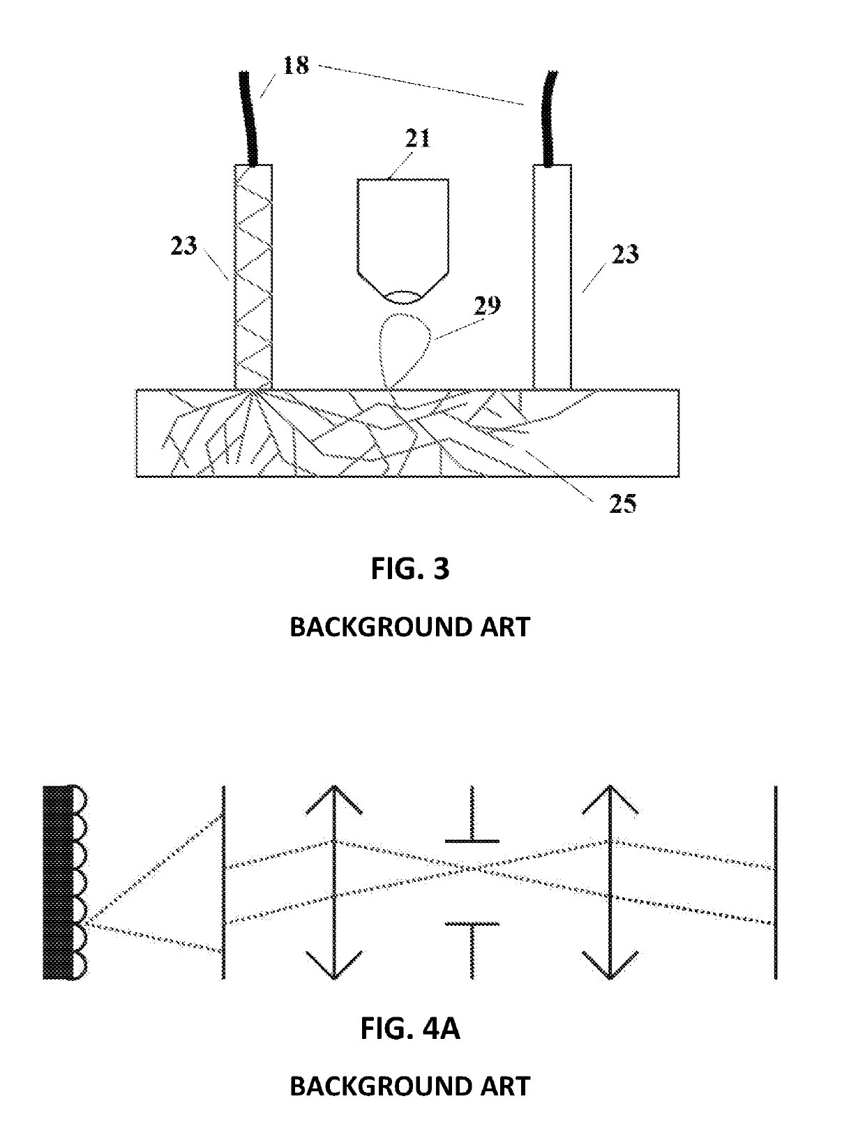
[0098]In a first embodiment, the light is passing through the sclera, the choroid and the retina. The transmitted and scattered light illuminates the fundus. In this variant, no or very little light is entering the pupil-lens. The light delivering device is in contact with the sclera. In other variant, transscleral in combination with transpupillary lighting can be used.

second embodiment

[0099]In a second embodiment, the light is passing through the skin layer near the eye, sclera, the choroid and the retina. The transmitted and scattered light illuminates the fundus. In this variant, no or very little light is entering the pupil-lens.

third embodiment

[0100]In a third embodiment, light is passing through the pupil, directed to the side of the eye. Here the rays are scattered and reflected towards the fundus.


PUM


Abstract

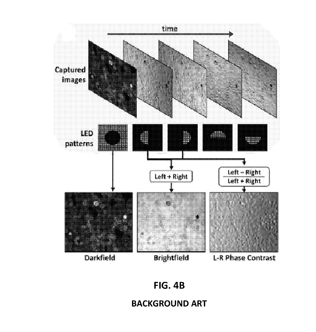
A method for imaging a tissue of an eye, the method including the steps of providing oblique illumination to the eye by a plurality of light emitting areas of a light delivery device, the plurality of light emitting areas being independently controllable and arranged to direct light towards at least one of a retina and an iris of the eye, causing an output beam from light backscattered from the at least one of the retina and the iris by the oblique illumination, capturing the output beam with an imaging system to provide a sequence of images of a fundus of the eye, and retrieving a phase and absorption contrast image from the sequence of images of the fundus, wherein the sequence of images of the fundus of the step of capturing is obtained by sequentially turning on one or more of the plurality of light emitting areas at a time in the step of providing the oblique illumination.

Description

CROSS-REFERENCE TO RELATED APPLICATIONS[0001]The present application claims priority to the International patent applications PCT / IB2016 / 052787 filed on May 13, 2016 and PCT / IB2016 / 056806 filed on Nov. 11, 2016, both of these patent applications herewith incorporated by reference in their entirety.FIELD OF THE INVENTION[0002]The present invention relates to high resolution quantitative and qualitative absorption, phase and dark field imaging of the retina by the use of oblique illumination.BACKGROUND[0003]Standard photography relies on the difference in absorption of different features for providing contrast. This is also the case in conventional funduscopy where blood vessels, photoreceptors and other retinal structures are observed thanks to their different reflectivity values that provide intensity modulation at the sensor plane. This is not the case for most of the cells lying in the inner retina (ganglions, nuclear and plexiform layers), whose absorption and scattering values a...

Claims


Application Information

Patent Timeline
IPC IPC(8): A61B3/12A61B3/00A61B3/14
CPCA61B3/14A61B3/12A61B3/0008
Inventor LAFOREST, TIMOTHÉCARPENTRAS, DINOMOSER, CHRISTOPHEKÜNZI, MATHIEUBEHAR-COHEN, FRANCINE
Owner ECOLE POLYTECHNIQUE FEDERALE DE LAUSANNE (EPFL)
Learn More