Reflective lamp to maximize light delivery to a photoactive catalyst

a photoactive catalyst and reflector technology, applied in the field of reflector lamps, can solve the problems of low photocatalytic efficiency of air purification system, misdirected light from lamps, and inability to absorb onto the photocatalytic coating, etc., and achieve the effect of maximizing light delivery

Active Publication Date: 2005-03-24
CARRIER CORP
View PDF4 Cites 27 Cited by
  • Summary
  • Abstract
  • Description
  • Claims
  • Application Information

AI Technical Summary

Benefits of technology

[0007] A reflective lamp utilized in a fluid purification system maximizes the light delivery to a photocatalytic coating that oxidizes gaseous contaminants that adsorb onto the surface to form carbon dioxide, water, and other substances.

Problems solved by technology

A drawback to employing filters is that they simply block the passage of contaminants and do not destroy them.
If only one monolith and one lamp or one bank of lamps are employed in the air purification system, much of the light from the lamp is misdirected and does not absorb onto the photocatalytic coating.
However, much of the light is still misdirected and not used for photocatalytic purposes.
Therefore, the photocatalytic efficiency for the air purification system is less than optimum.
However, adding a second monolith is costly and light is still misdirected from the lamp and not used for photocatalytic purposes.
Reflectors can be added adjacent to the lamp or bank of lamps to direct more of the light to the monolith, but this method adds an undesirable pressure drop to the system.

Method used


Image

  • Reflective lamp to maximize light delivery to a photoactive catalyst
  • Reflective lamp to maximize light delivery to a photoactive catalyst
  • Reflective lamp to maximize light delivery to a photoactive catalyst

Examples


Embodiment Construction

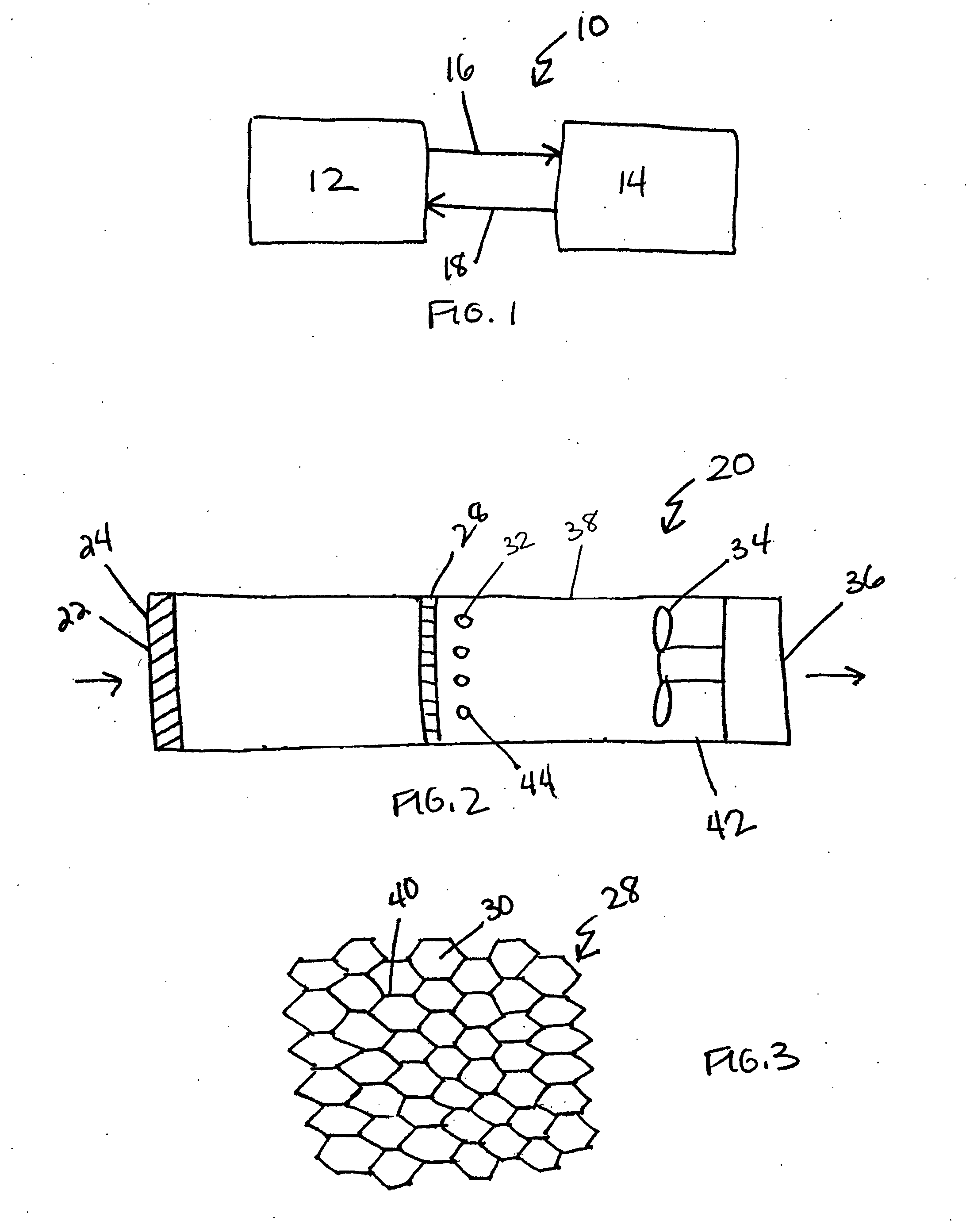
[0022]FIG. 1 schematically illustrates a building, vehicle, or other structure 10 including an interior space 12, such as a room, an office or a vehicle cabin, such as a car, train, bus or aircraft. An HVAC system 14 heats or cools the interior space 12. Fluid in the interior space 12, such as air, is drawn by a path 16 into the HVAC system 14. The HVAC system 14 changes the temperature of the fluid drawn 16 from the interior space 12. If the HVAC system 14 is operating in a cooling mode, the fluid is cooled. Alternately, if the HVAC system 14 is operating in a heating mode, the fluid is heated. The fluid is then returned back by a path 18 to the interior space 12, changing the temperature of the fluid in the interior space 12.

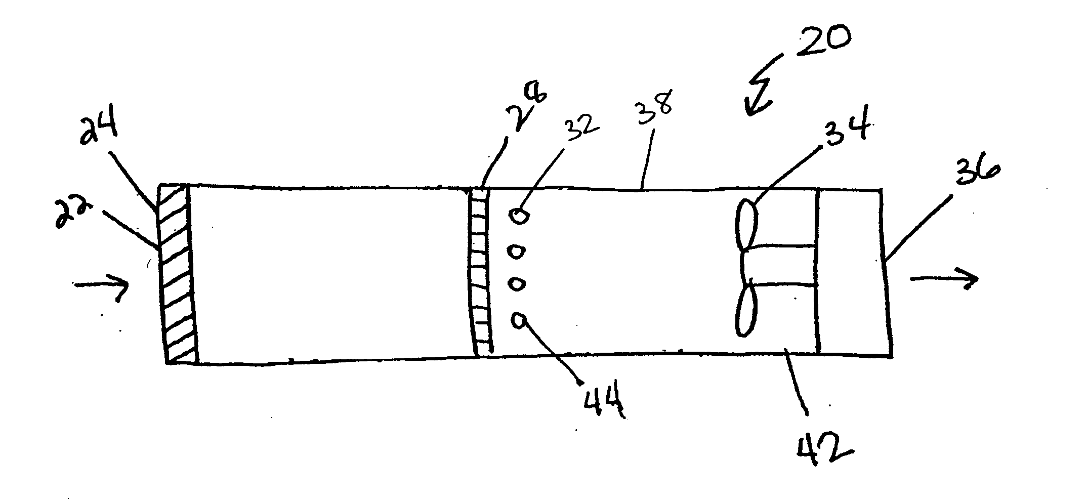
[0023]FIG. 2 schematically illustrates a fluid purification system 20 employed to purify the fluid in the building or vehicle 10 by oxidizing contaminants, such as volatile organic compounds and semi-volatile organic compounds, to water, carbon dioxide, and o...


PUM

PropertyMeasurementUnit
wavelengthaaaaaaaaaa
peak wavelengthaaaaaaaaaa

Abstract

A lamp including a reflective portion is utilized in a fluid purification system to maximize the light delivery to a photocatalytic coating that oxidizes gaseous contaminants that adsorb onto the surface to form carbon dioxide, water, and other substances. An ultraviolet light source positioned proximate to the honeycomb activates the titanium dioxide coating. In one example, the reflective portion is a reflective coating. Light directed out of the non-reflective portion of the lamp travels towards the honeycomb and absorbs onto the photocatalytic coating. Light directed towards the reflective portion on the lamp is reflected off the surface of the reflective portion and passes through the non-reflective portion of the lamp to also absorb onto the photocatalytic coating. The reflective portion reflects light towards the honeycomb that would otherwise be misdirected away from the honeycomb, increasing efficiency of the fluid purification system.

Description

BACKGROUND OF THE INVENTION [0001] The present invention relates generally to a reflective lamp utilized in a fluid purification system that maximizes the light delivery to a photocatalytic coating that oxidizes gaseous contaminants that adsorb onto the surface to form carbon dioxide, water, and other substances. [0002] Indoor air can include trace amounts of contaminants, including carbon monoxide and volatile organic compounds such as formaldehyde, toluene, propanal, butene, and acetaldehyde. Absorbent air filters, such as activated carbon, have been employed to remove these contaminants from the air. As air flows through the filter, the filter blocks the passage of the contaminants, allowing contaminant free air to flow from the filter. A drawback to employing filters is that they simply block the passage of contaminants and do not destroy them. [0003] Air purification systems commonly include one lamp or one bank of lamps and one photocatalytic monolith, such as a honeycomb. A p...

Claims


Application Information

Patent Timeline
Patent Type & Authority Applications(United States)
IPC IPC(8): A61L9/20B01D53/86B60H3/06F24F3/16
CPCA61L9/205B01D53/8668B01D2255/802B60H2003/0675F24F2003/1667C02F1/725C02F2305/10F24F3/166C02F1/32F24F8/192F24F8/22Y02A50/20
Inventor BENOIT, JEFFREY T.HAY, STEPHEN O.OBEE, TIMOTHY N.
Owner CARRIER CORP
Why Eureka
Try Eureka