Head-up display and moving object

a technology of moving objects and displays, applied in the field of heads-up displays, can solve the problems of increasing the size of the illumination optical system, and achieve the effect of high luminance and efficient display of a specific color

Pending Publication Date: 2019-09-26
PANASONIC INTELLECTUAL PROPERTY MANAGEMENT CO LTD
View PDF4 Cites 3 Cited by
  • Summary
  • Abstract
  • Description
  • Claims
  • Application Information

AI Technical Summary

Benefits of technology

[0006]According to a second aspect of the present disclosure, a moving object (an automobile vehicle, a railway vehicle, an aircraft, a ship, and so on) with the head-up display described above is provided. According to the head-up display of the present disclosure, lights emitted from a plurality of light source elemen...

Problems solved by technology

Therefore, it is necessary to separately secure optical paths of the first light and the second light, and th...

Method used


Image

  • Head-up display and moving object
  • Head-up display and moving object
  • Head-up display and moving object

Examples


first exemplary embodiment

[0026]A first exemplary embodiment will be described hereinafter with reference to the accompanying drawings.

[0027][1-1. Structure]

[0028][1-1-1. Overall Structure]

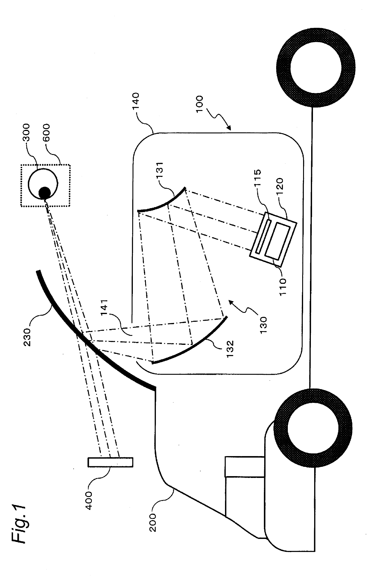
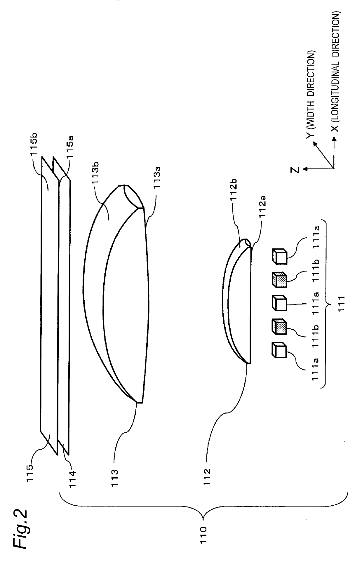
[0029]FIG. 1 is a view illustrating a structure of a head-up display mounted on a vehicle according to the first exemplary embodiment. A head-up display 100 is mounted on a vehicle 200 (an example of a moving object) including a windshield 230. The head-up display 100 includes a display unit 120, a reflective optical unit 130, and a housing 140. The display unit 120 includes a lighting device 110 and a liquid crystal panel 115.

[0030]The head-up display 100 is a device that projects an image for allowing an observer 300 to visually recognize a virtual image 400 onto the windshield 230.

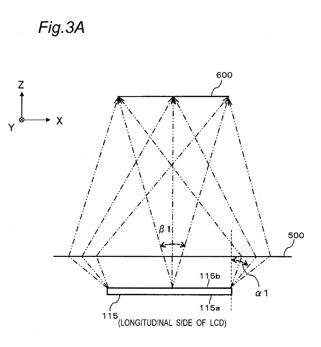
[0031]The lighting device 110 illuminates the liquid crystal panel 115 that is a display element. The liquid crystal panel 115 displays, for example, an image showing a speedometer or a numerical value indicating speed. The liquid crystal pane...

second exemplary embodiment

[0072][2-1. Structure]

[0073]According to the head-up display 100 of the present exemplary embodiment, as shown in FIG. 8, the arrangement of the first light source elements 111a and the second light source element 111b of the light source unit 111 and the diffusion angle of the diffusion plate 114 are different from those of the first exemplary embodiment, other structures are the same as those in the first exemplary embodiment.

[0074]In the display unit 120 of the head-up display 100 according to the present exemplary embodiment, the second light source element 111b is disposed only in a center of the light source unit 111. That is, the one second light source element 111b is arranged at a center of the four first light source elements 111a.

[0075]FIG. 9A is a view illustrating the angle characteristic in the X-axis direction of the light beams that enter the central portion of the diffusion plate 114 when the first light source elements 111a emit light, and FIG. 9B is a view illust...


PUM


Abstract

A head-up display includes a light source unit including first light source elements emitting lights of a first luminescent color and second light source elements emitting lights of a second luminescent color. The head-up display includes a first lens, a diffusion member, a spatial light modulation element that modulates the light emitted from the light source unit and transmitted through the first lens and the diffusion member, and an optical unit that projects the light emitted from the spatial light modulation element. The first lens changes an optical path of the light emitted from the light source unit, and the lights emitted from the first light source element and the second light source element are superimposed in a predetermined region on the incident surface of the spatial light modulation element.

Description

BACKGROUND1. Technical Field[0001]The present disclosure relates to a head-up display that displays an image for allowing a virtual image to be visually recognized from an observer's eye-box.2. Related Art[0002]JP 2010-276893 A discloses a head-up display in which emission lights from light sources having different luminescent colors behind a liquid crystal panel are superimposed by a polarizing member and transmitted illumination of the liquid crystal panel is performed. The head-up display includes a first light emitting element that emits a first light of a first color, a second light emitting element that emits a second light of a second color, and the polarizing member that reflects an illumination light. Thereby, the head-up display in which a display light has a desired chromaticity is provided.SUMMARY[0003]According to the head-up display of Patent Literature 1, the polarizing member that reflects the illumination light is used in order to superimpose the first light of the ...

Claims


Application Information

Patent Timeline
IPC IPC(8): G02B27/01G02F1/1335B60K35/00B60J1/20
CPCG02F1/133603G02B2027/0112G02F1/133606G02B2027/0118B60K35/00G02F2001/133607B60J1/20B60K2370/29B60K2370/33G02B27/0101G02B2027/0141G02B5/02G02B19/0014G02F1/133607
Inventor ASAI, YOSUKE
Owner PANASONIC INTELLECTUAL PROPERTY MANAGEMENT CO LTD
Why Eureka
Try Eureka