Supercharge Your Innovation With Domain-Expert AI Agents!

Industrial Device Image Recognition Processor and Controller

a technology applied in the field of image recognition processors for industrial devices and controllers, can solve the problems of low practicability of image recognition processing in the application case of such industrial devices as in factory automation, and achieve the effects of reducing power consumption, improving processing speed, and reducing weigh

Active Publication Date: 2019-09-26
YASKAWA DENKI KK
View PDF0 Cites 8 Cited by
  • Summary
  • Abstract
  • Description
  • Claims
  • Application Information

AI Technical Summary

Benefits of technology

The present invention aims to provide an image recognition processor and controller for industrial devices that can improve the practical applicability of image recognition processing. This means that the invention aims to make image recognition processing more useful in industrial settings.

Problems solved by technology

However, a processing device itself, which is configured to perform image recognition, has used a server via a network or a processing device of a large circuit scale, and hence practical applicability of image recognition processing in a case of application to such an industrial device as in factory automation has been low.

Method used


Image

  • Industrial Device Image Recognition Processor and Controller
  • Industrial Device Image Recognition Processor and Controller
  • Industrial Device Image Recognition Processor and Controller

Examples


modification example

[0061]Note that, the above-described embodiments are not limited to the above-mentioned embodiment, and various modifications are possible within the range not departing from the gist and technical concept thereof.

modification example 1

mera and the Image Recognition Processor are Installed on the Arm Distal End Portion

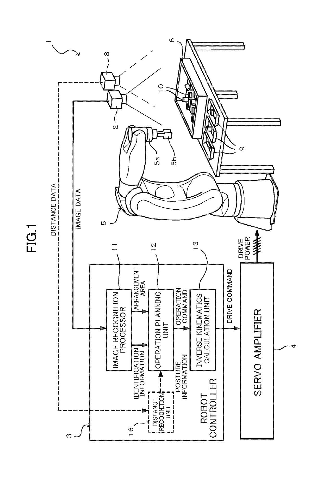
[0062]For example, in the above-mentioned embodiment, the image data has been acquired by fixed-point imaging in which the camera 2 is fixed, but the present invention is not limited thereto. For example, as illustrated in FIG. 6, the camera 2 may be fixed on the arm distal end portion 5a of a six-axis robot 5A, and a shape of a detailed part forming a target structure 21 may be imaged from various lines of sight to perform assembly inspection of the structure 21.

[0063]In this case, the image recognition processor 11 recognizes, from the image data, a pattern of the detailed part to be inspected, and outputs the identification information and the arrangement areas. Based on the identification information and the arrangement areas, an inspection device 7 determines an inspection result. Moreover, the inspection device 7 outputs coordinate information of the detailed part, on the basis of which a robot...

modification examples

Other Modification Examples

[0067]Moreover, although not particularly shown, as optical sensing means for acquiring the image data of the object, a laser scanner or the like may be used instead of the camera 2 (and the three-dimensional sensor 8). In this case, a distance to each point on the surface of the object is measured with a scanning line projected by the laser scanner, and the image data is acquired as a set of distance data, for example.

[0068]In the above description, when the terms “vertical”, “parallel”, and “planar” are used, the terms are not used in a strict sense. In other words, the terms “vertical”, “parallel”, and “planar” allow design and manufacturing tolerances and errors, and mean “substantially vertical”, “substantially parallel”, and “substantially planar”.

[0069]Moreover, in the above description, when apparent dimensions, size, shape, position, and the like are described as “the same”, “identical”, “equal”, and “different”, the terms are not used in a strict...


PUM


Abstract

An image recognition processor for an industrial device, the image recognition processor implementing, on an integrated circuit thereof, the functions of storing an image data processing algorithm, which has been determined based on prior learning; acquiring image data of an image including a predetermined pattern; and performing recognition processing on the image data based on the image data processing algorithm to output identification information for identifying a recognized pattern.

Description

CROSS-REFERENCE TO RELATED APPLICATION[0001]The present application is continuation of International Application No. PCT / JP 2017 / 036974 filed on Oct. 12, 2017, which claims priority from Japanese Application No. JP 2016-245763 filed on Dec. 19, 2016. The contents of these applications are hereby incorporated by reference into this application.BACKGROUND OF THE INVENTION1. Field of the Invention[0002]An embodiment of this disclosure relates to an image recognition processor for an industrial device and a controller.2. Description of the Related Art[0003]In Japanese Patent Application Laid-open No. 2011-235386, there is described a control device configured to recognize a grasping-target object, for example, based on imaging information of a camera provided on a hand of a robot arm.SUMMARY OF THE INVENTION[0004]However, a processing device itself, which is configured to perform image recognition, has used a server via a network or a processing device of a large circuit scale, and henc...

Claims


Application Information

Patent Timeline
IPC IPC(8): G06T7/00G06K9/00G06K9/62G06N3/08G06V10/764
CPCG06T7/0004G06N3/08G06K9/6256G06K9/00523G06V10/454G06V2201/06G06V10/82G06V10/764G06F18/2431G06F18/214G06F2218/08
Inventor ADACHI, MASARU
Owner YASKAWA DENKI KK
Features
  • R&D
  • Intellectual Property
  • Life Sciences
  • Materials
  • Tech Scout
  • Unparalleled Data Quality
  • Higher Quality Content
  • 60% Fewer Hallucinations
Learn More