Vehicle power supply system

a technology for power supply systems and vehicles, applied in the direction of motor/generator/converter stoppers, electric generator control, dynamo-electric converter control, etc., can solve problems such as the concern of deterioration of efficiency in the vehicle power supply system

Active Publication Date: 2019-10-03
HONDA MOTOR CO LTD
View PDF0 Cites 9 Cited by
  • Summary
  • Abstract
  • Description
  • Claims
  • Application Information

AI Technical Summary

Benefits of technology

[0006]According to an embodiment of the disclosure, there is provided a vehicle power supply system including: a first motor generator connected to a first wheel of a vehicle; a second motor generator connected to a second wheel; a first circuit to which a first power converter that transfers power to and from the first motor generator and a first power storage device are connected; a second circuit to which a second power converter that transfers power to and from the second motor generator and a second power storage device are connected; a voltage converter that converts a voltage between the first circuit and the second circuit; a total required power acquisition unit that acquires total required power that is required in the first and second circuits; and a charging and discharging control device that controls charging and discharging of the first and second power storage devices by operating the first and second power converters and the voltage converter, wherein, in a case where the total required power is larger than first outputtable power that is power capable of being output by the first power storage device, the charging and discharging control device discharges a shortage of power from the second power storage device to the second circuit, wherein the shortage of power is obtained by excluding an amount that is output by the first power storage device from the total required power.

Problems solved by technology

However, since substantial loss of power occurs in the converter when power passes through the converter, there may be a concern of efficiency deteriorating in the vehicle power supply system disclosed in Patent Document 1.

Method used


Image

  • Vehicle power supply system
  • Vehicle power supply system
  • Vehicle power supply system

Examples


Embodiment Construction

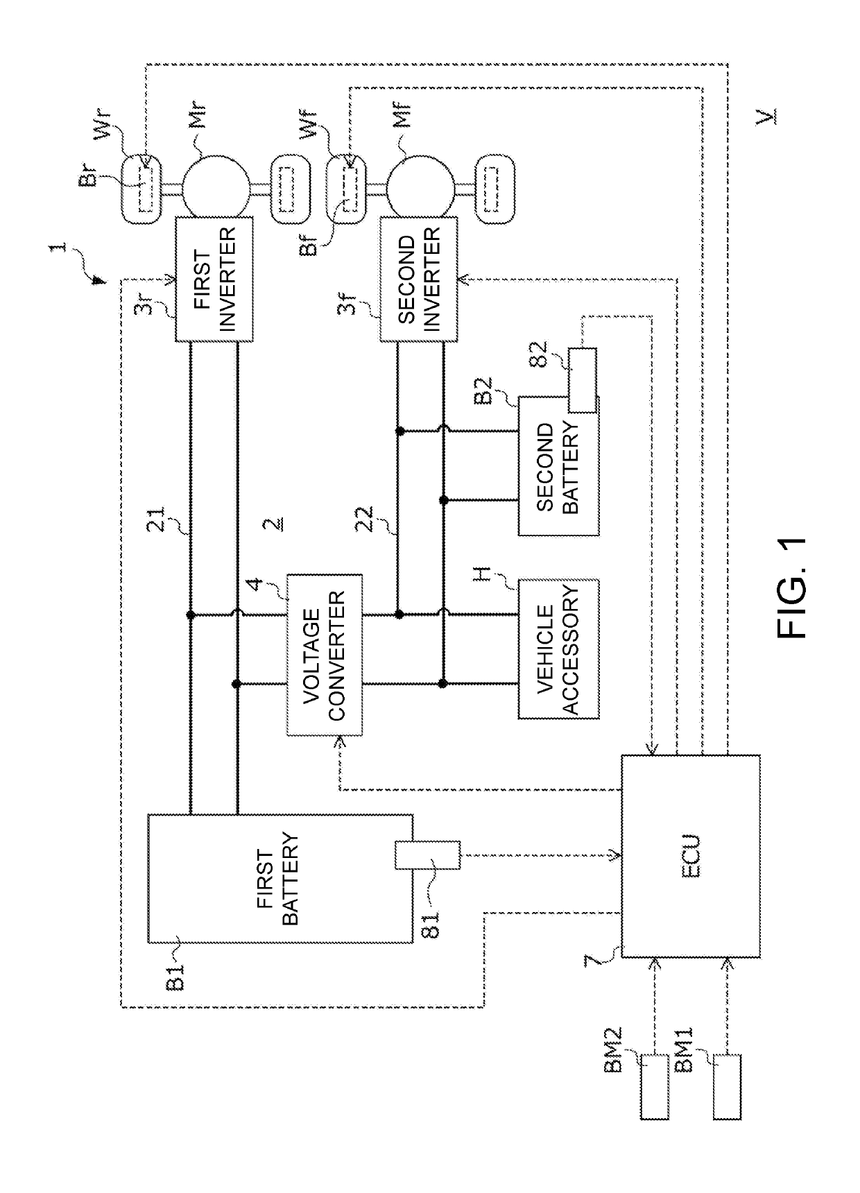
[0043]The disclosure provides a vehicle power supply system including two power storage devices and a voltage converter which makes it possible to perform high-output traveling while reducing loss in a voltage converter.

[0044](1) According to an embodiment of the disclosure, there is provided a vehicle power supply system including: a first motor generator connected to a first wheel of a vehicle; a second motor generator connected to a second wheel; a first circuit to which a first power converter that transfers power to and from the first motor generator and a first power storage device are connected; a second circuit to which a second power converter that transfers power to and from the second motor generator and a second power storage device are connected; a voltage converter that converts a voltage between the first circuit and the second circuit; a total required power acquisition unit that acquires total required power that is required in the first and second circuits; and a c...


PUM


Abstract

A power supply system includes a first drive motor, a second drive motor, a first power line to which a first inverter and a first battery are connected, a second power line to which a second inverter and a second battery are connected, a voltage converter that converts a voltage between the first power line and the second power line, and an ECU that operates the first and second inverters and and the voltage converter and controls charging and discharging of the first and second batteries. In a case where total required power is larger than first outputtable power of the first battery, the ECU discharges a shortage of power from the second battery to the second power line, wherein the shortage of power is obtained by excluding an amount that is output by the first battery from the total required power.

Description

CROSS-REFERENCE TO RELATED APPLICATION[0001]This application claims the priority benefit of Japan Application No. 2018-069973, filed on Mar. 30, 2018. The entirety of the above-mentioned patent application is hereby incorporated by reference herein and made a part of this specification.BACKGROUNDTechnical Field[0002]The disclosure relates to a vehicle power supply system. More specifically, the disclosure relates to a vehicle power supply system including two power storage devices and a voltage converter.Description of Related Art[0003]In recent years, the development of electromotive transport instruments including an electric motor as a motive power generation source or electromotive vehicles such as a hybrid vehicle including an electric motor and an internal-combustion engine as a motive power generation source has been actively performed. In such electromotive vehicles, an electric condenser such as a battery or a capacitor is also mounted in order to supply electrical energy t...

Claims


Application Information

Patent Timeline
Patent Type & Authority Applications(United States)
IPC IPC(8): B60L50/60H02P5/74H02J7/14B60L1/00B60L3/12B60L53/20B60L58/18B60L50/51
CPCB60L50/60H02J7/1423B60L2210/14B60L2210/40B60L53/20H02P5/74B60L3/12H02J2007/143B60L1/00B60L50/51B60L58/18B60L2240/54H02P4/00H02P3/18H02P2101/45H02P2201/07H02P27/14H02J7/143Y02T10/64Y02T10/72Y02T10/70Y02T90/14Y02T10/7072Y02T90/12H02J7/0013H02J7/0048H02J7/0047
Inventor OYAMA, KAZUYAOTSUKI, YUTOOGUMA, HIROKAZU
Owner HONDA MOTOR CO LTD
Why Eureka
Try Eureka