Device for detecting positional relationship among objects

a technology of positional relationship and device, applied in the field of device for positional relationship among objects, can solve the problems of narrow space for positioning product identification information, difficult to recognize positional relationship among products, and inability to identify the position of product identification information between a set of positional identification information, etc., to achieve easy recognition, improve work efficiency, and easy to check

Active Publication Date: 2019-10-03
DENSO WAVE INC
View PDF0 Cites 27 Cited by
  • Summary
  • Abstract
  • Description
  • Claims
  • Application Information

AI Technical Summary

Benefits of technology

[0021]In the above aspect of the disclosure, since all the information codes are formed in the same size, obtaining the size of one information code is sufficient to obtain the size of the other information codes. Accordingly, in detection of the relative positional relationship, the detection processing load can be reduced.
[0022]In the above aspect of the disclosure, an information code in which first end information indicative of a first end in a longitudinal direction is recorded is provided on the shelf board at a position on the first end in the longitudinal direction of the display shelf, and another information code in which second end information indicative of a second end in a longitudinal direction is recorded is provided on the shelf board at a position on the second end in the longitudinal direction of the display shelf. The first end information read by the reading unit and the second end information read by the reading unit are stored in the storage unit. Accordingly, when both the first end information and the second end information are recorded in the storage unit, it is possible to easily assume that the imaging range has been moved from the first end to the second end in the longitudinal direction of the display shelf, and thus all the information codes provided on the display shelf have been read.
[0023]In the above aspect of the disclosure, it is possible not only to recognize the display shelf from the first end to the second end in the longitudinal direction, but to easily recognize for which display shelf the detection of positional relationship among the items is being performed, since at least one of the first end information and the second end information includes the shelf information that specifies the display shelf.
[0030]In the above aspect of the disclosure, the item images in which items are captured are associated with the specific information and pre-stored in the storage unit for each of the items. Then, the panoramic image generated by the generation unit and a plurality of item images stored in the storage unit are compared with each other so that the display ranges in which the items are displayed are specified by the specifying unit for each of the items in the panoramic image. In the display unit, the plurality of display ranges thus specified are indicated in the panoramic image. Accordingly, since the respective display ranges of the items can be indicated in the panoramic image of the display shelf, the display state of the respective items can be easily recognized. In addition, the number of the displayed items can be easily checked by using the panoramic image.
[0031]In the above aspect of the disclosure, an obtaining unit externally obtains the item image for each of the specific information by using the specific information read by the reading unit, and stores the item image in the storage unit. Accordingly, the need to pre-store the item images in the storage unit for the items expected to be displayed is eliminated to thereby improve the work efficiency.
[0032]In the above aspect of the disclosure, at least part of the panoramic image is enlargeable on the display unit. Accordingly, the display range of a desired item can be enlarged to thereby more accurately recognize the display state of the items and check the number of items.

Problems solved by technology

The configuration disclosed in JP-A-2016-194833 has a problem that the position of product identification information between a set of positional identification information cannot be identified unless an image of the set of positional identification information is captured.
Accordingly there is a problem that, when the pieces of positional identification information are spaced by a short distance from each other, a space for positioning product identification information is narrow.
In particular, since a display shelf provided in a store often has an elongated shape extending along an aisle, it is difficult to recognize positional relationship among the products when an image of such a display shelf cannot be captured in one captured image.
However, in connection of the captured images, it is not clear whether all the information codes disposed on the display shelf are captured and readable.
In this case, another image needs to be captured again, which is inefficient.
Although the relative positional relationship between the information codes can be proportionally recognized from a plurality of pieces of relative position information stored in the storage unit, the actual distance and dimensions cannot be accurately calculated only from the captured image.

Method used


Image

  • Device for detecting positional relationship among objects
  • Device for detecting positional relationship among objects
  • Device for detecting positional relationship among objects

Examples


first embodiment

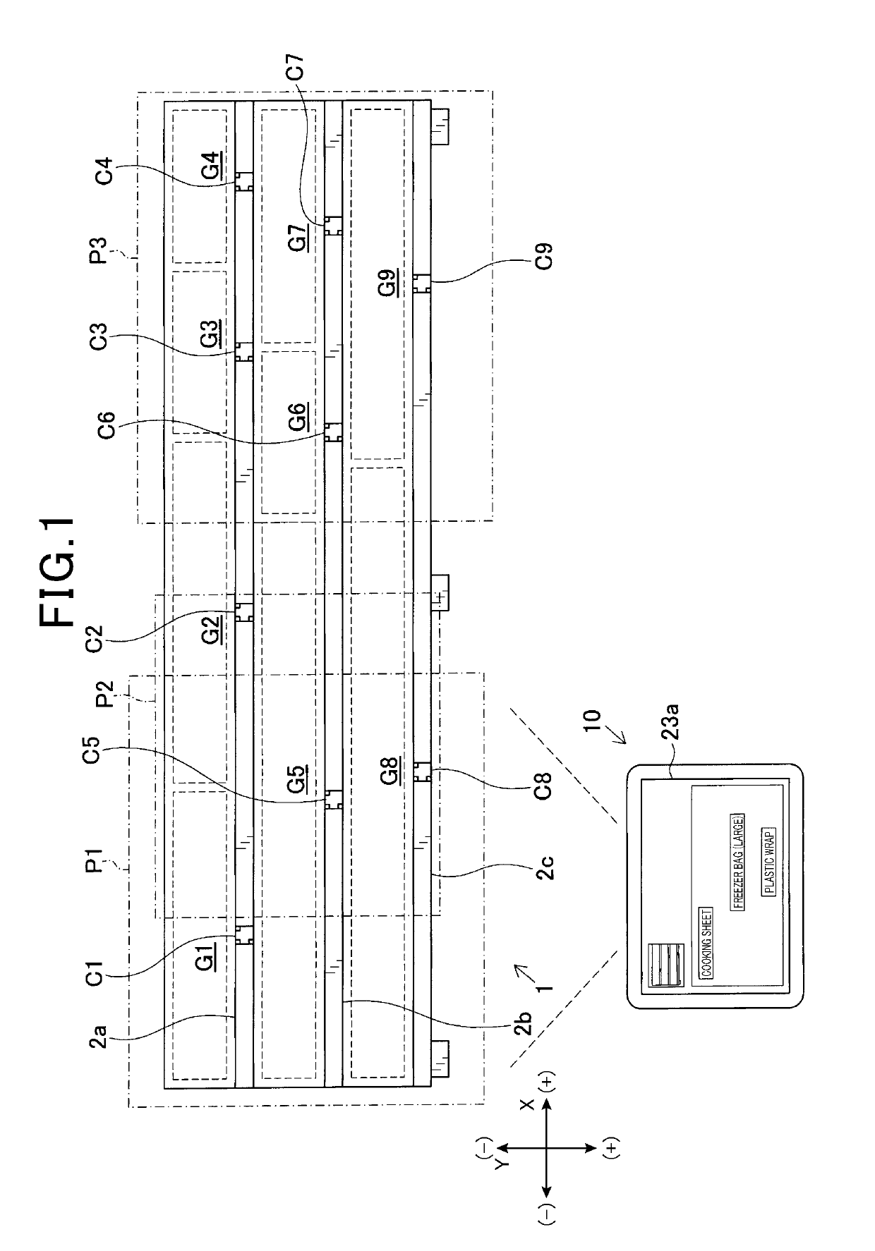
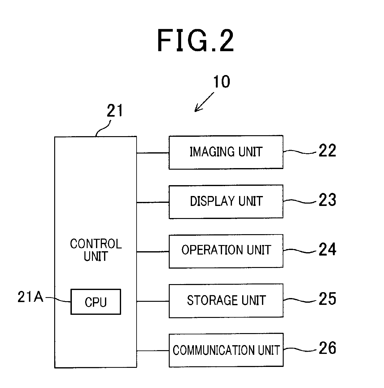
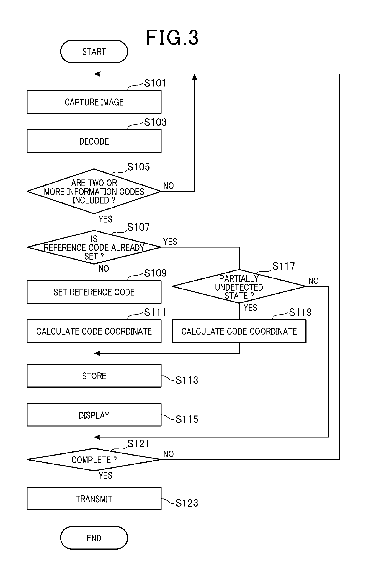
[0053]With reference to the drawings, a first embodiment in which a positional relationship detection device according to the present invention is applied to a mobile terminal will be described. The positional relationship detection device is provided as a device for detecting positional relationships among objects being detected.

[0054]A mobile terminal 10 shown in FIG. 1 is provided as a positional relationship detection device for detecting positional relationship among a plurality of items (i.e., objects being detected) displayed on a display shelf 1 by using information codes. In this embodiment, positional relationship among the products displayed on the display shelf 1 shown in FIG. 1 is a detection target. The display shelf 1, which is horizontally (that is, the width direction X later described) elongated along an aisle, is vertically partitioned by three shelf boards 2a to 2c.

[0055]As shown in FIG. 1, the display shelf 1 can be given the width direction extending in the ho...

second embodiment

[0092]Next, with reference to the drawings, a mobile terminal according to a second embodiment will be described. The second embodiment differs from the first embodiment mainly in that two information codes indicative of both ends in the longitudinal direction (i.e, the width direction X) of the display shelf 1 are additionally provided. Therefore, components which are substantially the same as those of the first embodiment are denoted by the same reference signs, and the description thereof will be omitted.

[0093]In the present embodiment, as illustrated in FIG. 9, a first end code Ca is provided on the shelf board 2a at a position on a first end in the longitudinal direction (i.e, the width direction X) of the display shelf 1 as an information code in which first end information indicative of a first end in the longitudinal direction is recorded. Further, a second end code Cb is provided on the shelf board 2c at a position on a second end in the longitudinal direction of the displa...

third embodiment

[0099]Next, with reference to the drawings, a mobile terminal according to a third embodiment will be described. The third embodiment differs from the second embodiment mainly in that the actual distance or the like between the respective information codes is calculated while the size (actual dimensions) of the respective information codes provided on the display shelf is not obtained. Therefore, components which are substantially the same as those of the second embodiment are denoted by the same reference signs, and the description thereof will be omitted.

[0100]In the present embodiment, even in the case where the sizes of the respective information codes provided on the display shelf are not directly obtained, the code image size of the reference code described above in the captured image (an area occupied by the reference code in the captured image) can be used to detect the size ratio of the other information codes relative to the reference code and detect the relative positions...


PUM


Abstract

Information codes each having a predetermined size, in which specific information for specifying the type of item is recorded, are provided by using shelf boards at positions where the respective types of the items are displayed on a display shelf. When two or more information codes whose specific information is read are included in one captured image captured by an imaging unit while no detected code is stored in the storage unit, the relative positional relationship among the two or more information codes is detected based on the sizes of the information codes. Further, when the captured image is determined as a partially undetected state, in which an undetected code is included together with at least one detected code, the relative positional relationship of the undetected code relative to the detected code is detected based on the size of the reference code.

Description

CROSS-REFERENCE TO RELATED APPLICATION[0001]This application is based on and claims the benefit of priority from earlier Japanese Patent Applications No. 2018-060268 filed Mar. 27, 2018, No. 2018-104393 filed May 31, 2018, and No. 2018-168798 filed Sep. 10, 2018, the descriptions of which are incorporated herein by reference.BACKGROUNDTechnical Field[0002]The present invention relates to a device for a positional relationship among objects, and in particular, to the device for detecting a positional relationship among items, provided as the objects, displayed on a display shelf by using information codes.Related Art[0003]In management of the products displayed on display shelves, there has been a demand for recognition of positional relationship among the products in the display shelf. There have been known techniques related to positional relationship detection devices for detecting positional relationship among the products and the like displayed on the display shelves.[0004]For e...

Claims


Application Information

Patent Timeline
Patent Type & Authority Applications(United States)
IPC IPC(8): G06T7/73G06T3/40G06K7/14G06K19/06
CPCG06T3/4038G06T2207/30204G06T7/74G06K19/06037G06K7/1417G06Q10/087G06V10/462
Inventor YODA, TAKUYARYO, TSU
Owner DENSO WAVE INC
Why Eureka
Try Eureka