Power Module Having Reduced Susceptibility to Defects, and Use Thereof

Pending Publication Date: 2019-10-03
TDK ELECTRONCS AG
View PDF8 Cites 6 Cited by
  • Summary
  • Abstract
  • Description
  • Claims
  • Application Information

AI Technical Summary

Benefits of technology

[0007]Embodiments provide power modules having a reduced susceptibility to

Problems solved by technology

Correspondingly, there is an increase in their complexity, and thus in the number of possibilities of a defect.
In addition, the trend towards miniaturization is continuing, with the result that the structural spa

Method used


Image

  • Power Module Having Reduced Susceptibility to Defects, and Use Thereof
  • Power Module Having Reduced Susceptibility to Defects, and Use Thereof
  • Power Module Having Reduced Susceptibility to Defects, and Use Thereof

Examples


Example

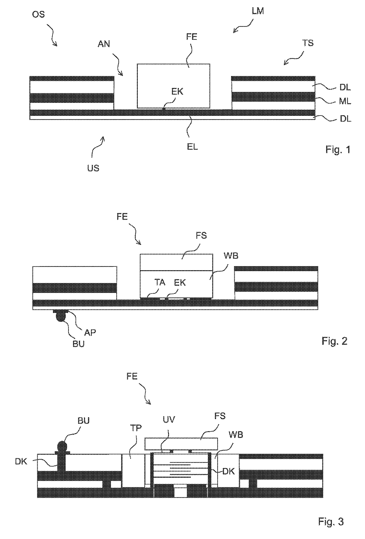
[0065]FIG. 1 shows the basic structure of a power module LM, having a carrier substrate TS that comprises a plurality of layers. These include, in particular, dielectric layers DL of an insulating material, and metallization layers ML, in which electrical structures can be formed. In the carrier substrate TS there is a recess AN, in which the functional element FE is arranged. The recess shown in FIG. 1 has the shape of a so-called blind hole, i.e., the recess has a base. The functional element FE sits on the base of the recess. In the case of a power module LM having a recess AN that is open only in one direction, the side toward which the recess AN is open is the upper side OS. The opposite side is the underside US.

[0066]The functional element FE is interconnected, via an electrical contact EK, with the electrical conductor EL, e.g., formed in a metallization layer.

[0067]Heat that is formed in the functional element FE, in particular on the upper side of the functional element FE,...


PUM


Abstract

A power module is disclosed. In an embodiment a power module includes a carrier substrate having a dielectric layer, a metallization layer and a recess and an electrical functional element, wherein the metallization layer includes a structured electrical conductor, wherein the functional element is interconnected with the electrical conductor, wherein the functional element is arranged in the recess, and wherein the functional element includes a thermal bridge that has a greater thermal conductivity than the carrier substrate.

Description

[0001]This patent application is a national phase filing under section 371 of PCT / EP2017 / 077010, filed Oct. 23, 2017, which claims the priority of German patent application 102016122014.0, filed Nov. 16, 2016, each of which is incorporated herein by reference in its entirety.TECHNICAL FIELD[0002]The invention relates to power modules.BACKGROUND[0003]Increasingly more electrical and electronic components are being used in technical devices. Correspondingly, there is an increase in their complexity, and thus in the number of possibilities of a defect. In addition, the trend towards miniaturization is continuing, with the result that the structural space for realizing electrical and electronic functions is becoming ever smaller.[0004]Electrical and electronic functions are often realized by electrical modules. A module generally combines a plurality of electrical components, e.g., chips, on a carrier substrate. Such modules are known, for example, from US patent applications publicatio...

Claims


Application Information

Patent Timeline
IPC IPC(8): H01L33/64H01L25/16H05K1/02H05K1/18
CPCH01L25/167H05K1/0204H05K2201/10106H05K2201/10196H05K1/0259H05K1/183H01L33/647H05K1/0209H05K2201/0187H05K2201/0738
Inventor FEICHTINGER, THOMAS
Owner TDK ELECTRONCS AG
Why Eureka
Try Eureka