Electroporation systems and catheters for electroporation systems

a technology of electroporation system and electroporation catheter, which is applied in the field of medical devices, can solve problems such as death and variety of ailments

Pending Publication Date: 2019-10-10
ST JUDE MEDICAL CARDILOGY DIV INC
View PDF3 Cites 17 Cited by
  • Summary
  • Abstract
  • Description
  • Claims
  • Application Information

AI Technical Summary

Benefits of technology

[0008]In another embodiment, the present disclosure is directed to a method of controlling an electroporation system including a monophasic energy source, a return electrode connected to the monophasic energy source, and a catheter connected to the monophasic energy source. The catheter has an electrode surface area. The method includes determining a system impedance with the patch electrode on a body and the catheter positioned within the body adjacent a target area. The system imp

Problems solved by technology

Arrhythmia (i.e., irregular heart rhythm) can create a variety of dangerous conditions including loss of synchron

Method used


Image

  • Electroporation systems and catheters for electroporation systems
  • Electroporation systems and catheters for electroporation systems
  • Electroporation systems and catheters for electroporation systems

Examples


example 1

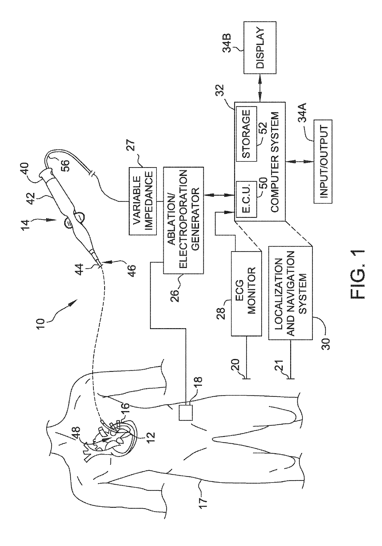
[0063]An example implementation of system 10 was constructed and tested. FIG. 4 is a simplified diagram of the example system 400. In the example system 400, generator 26 is the Lifepak 9 defibrillator described above. A junction box 402 is used to connect generator 26 (and variable impedance 27) to catheter 14 and return electrode 18. Catheter 14 is a fifteen mm diameter hoop catheter with ten electrodes of two mm length. The surface area of the electrodes is about one hundred forty six square millimeters. Return electrode 18 is a four cm square stainless steel mesh with a much larger surface area than that of the catheter electrodes. The voltage and current supplied to catheter 14 are detected at junction box 402 and monitored by a computing device 404.

[0064]Some tests of this implementation were performed with catheter 14 and the return 18 in a tank 406 having a diameter of eleven centimeters (cm). Other tests were performed with the catheter 14 and return 18 in an in vivo pig mo...

example 2

[0070]A second example implementation of system 10 was constructed and tested. The second implementation is the same as the example system 400, but uses a different catheter 14. In the second implementation, catheter 14 is a fourteen electrode hoop catheter with 2.5 mm ring electrodes and a 15-28 mm adjustable hoop size. The electrodes have a surface area of about two hundred fifty six square millimeters.

[0071]FIG. 10 shows saline tank data with evidence of arcing (the bump in the impedance trace) when a two hundred joules shock is applied by generator 26 with variable impedance 27 at zero. When the system impedance is increased by ten ohms using variable impedance 27, the traces (right side) do not show any sign of arcing when a two hundred joule shock is applied. The tests were repeated multiple times to collect multiple current, voltage, and calculated resistance traces from two hundred joule shocks in the saline tank. Based on test data, a target impedance for the system impedan...


PUM


Abstract

The present disclosure provides electroporation systems, methods of controlling electroporation systems to limit electroporation arcs through intracardiac catheters, and catheters for electroporation systems. One method of controlling an electroporation system including a direct current (DC) energy source, a return electrode connected to the DC energy source, and a catheter connected to the DC energy source is disclosed. The catheter has a at least one catheter electrode. The method includes positioning the return electrode near a target location within a body and positioning the catheter electrode adjacent the target location within the body. A system impedance is determined with the return electrode positioned near the target location and the catheter electrode positioned within the body. The system impedance is adjusted to a target impedance to arcing from the catheter electrode.

Description

CROSS REFERENCE TO RELATED APPLICATIONS[0001]This application claims priority to provisional application Ser. No. 62 / 427,190, filed Nov. 29, 2016, provisional application Ser. No. 62 / 427,195, filed Nov. 29, 2016, and provisional application Ser. No. 62 / 431,735, filed Dec. 8, 2016, all of which are incorporated herein by reference in their entirety.A. FIELD OF THE DISCLOSURE[0002]The present disclosure relates generally to medical devices that are used in the human body. In particular, in many embodiments, the present disclosure relates to electroporation systems and methods of controlling electroporation systems to limit electroporation arcs from catheters. Further, the present disclosure relates to systems and methods for identifying such arcs.B. BACKGROUND[0003]It is generally known that ablation therapy may be used to treat various conditions afflicting the human anatomy. One such condition in which ablation therapy finds a particular application in, for example, is the treatment...

Claims


Application Information

Patent Timeline
IPC IPC(8): A61B18/12A61B18/14
CPCA61B2018/00875A61B18/1233A61B2018/1266A61B2018/1407A61B2018/167A61B18/1492A61B5/0422A61B2018/00351A61B2018/00755A61B2018/1435A61B2018/00613A61B2034/2053A61B2018/00375A61B2018/00577A61B2018/00839A61B34/20A61B2034/2051A61B5/287
Inventor BYRD, ISRAELFISH, JEFFREY M.SCHWEITZER, JEFFREY A.POTTER, DANIEL J.OLSON, GREGORY K.WITTKAMPF, FREDERIK H. M.VAN ES, RENE
Owner ST JUDE MEDICAL CARDILOGY DIV INC
Why Eureka
Try Eureka