
LC-Column with Dynamic-Axial Compression (DAC)

a technology of dynamic-axial compression and column furnace, which is applied in the direction of separation processes, instruments, measurement devices, etc., can solve the problems of major disadvantage, excessively long predecessor patent version usually does not fit in the column furnace,

Active Publication Date: 2019-10-10
ALBIN MAISCH HIGH PERFORMANCE LC
View PDF0 Cites 1 Cited by
  • Summary
  • Abstract
  • Description
  • Claims
  • Application Information

AI Technical Summary

Benefits of technology

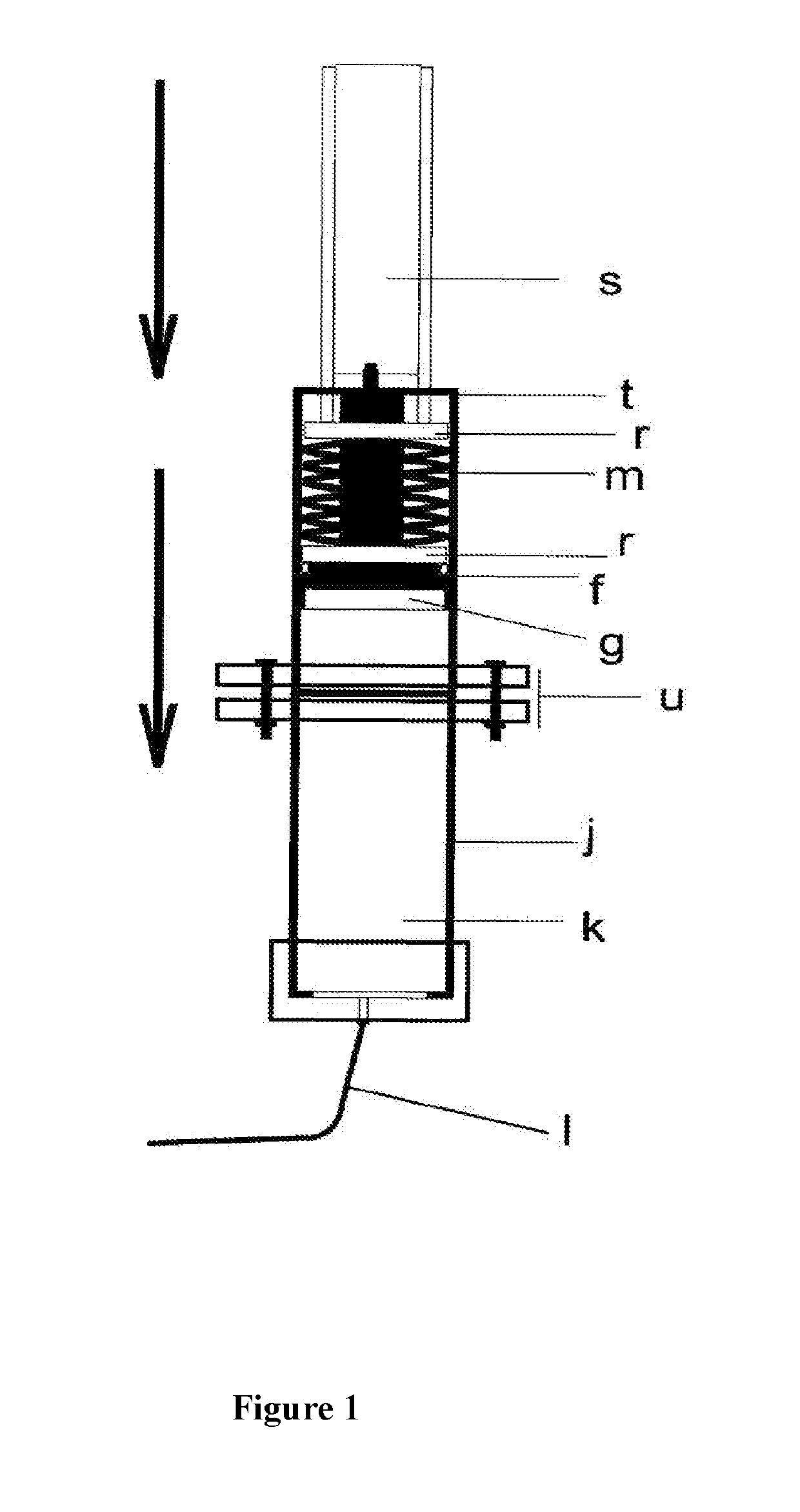
The patent text describes a new type of column that solves two problems: it can be used in column furnaces and it saves materials, is cheaper, and is more convenient. Compared to other methods, it has a higher quality. The column uses a spring that compresses during the packing process and pushes the column stamp onto the packing. The spring maintains a constant pressure on the column bed, preventing any cavity between the stamp and bed that could compromise the column quality. Thus, the new column overcomes its disadvantages and achieves better performance.

Problems solved by technology

The excessively long predecessor patent version usually does not fit in these column furnaces, which is a major disadvantage.

Method used


Image

  • LC-Column with Dynamic-Axial Compression (DAC)
  • LC-Column with Dynamic-Axial Compression (DAC)
  • LC-Column with Dynamic-Axial Compression (DAC)

Examples


Embodiment Construction

[0042]An LC column generally consists of the column tube which contains the actual chromatographic packing (column bed), the column inlet and the column outlet:

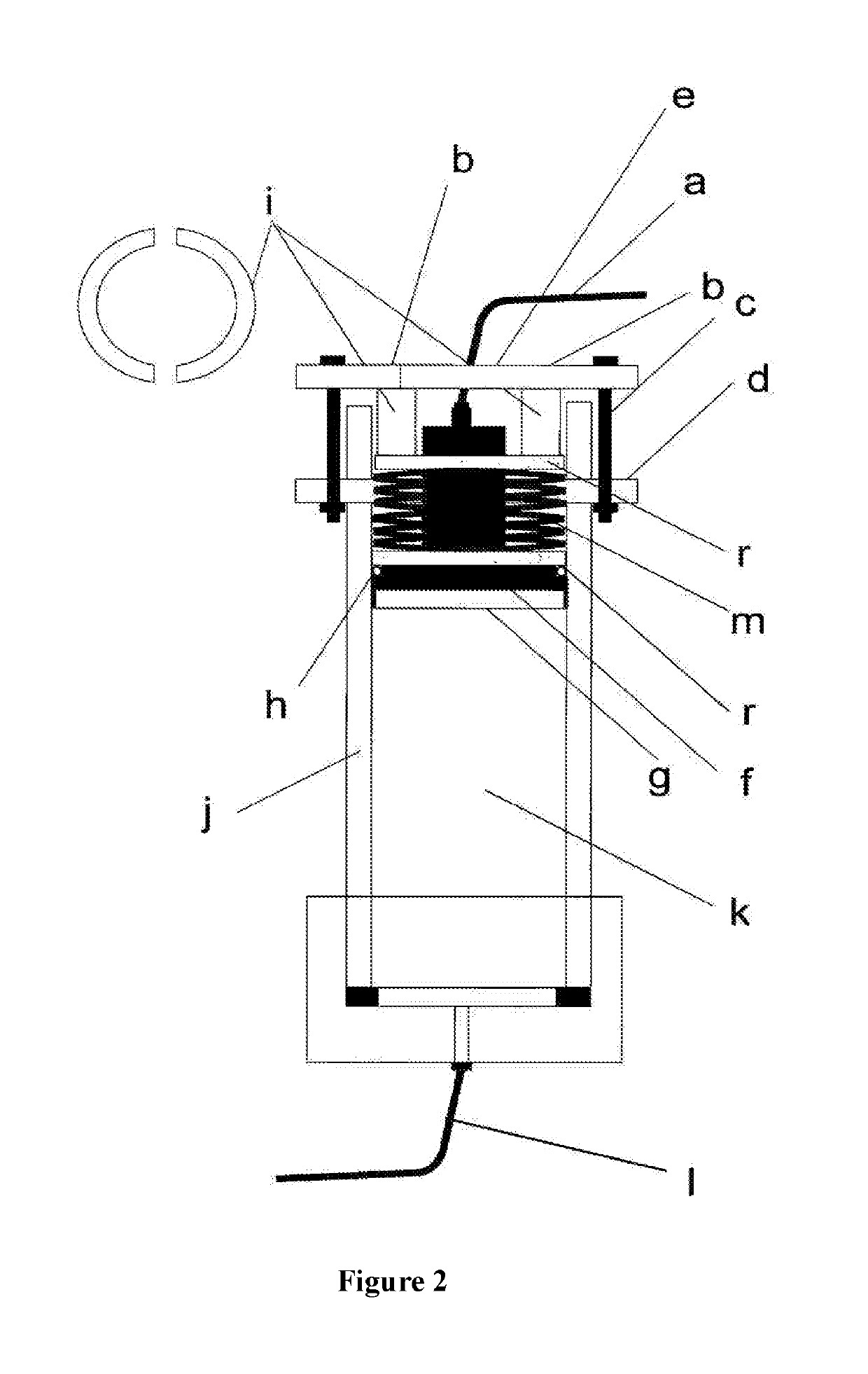
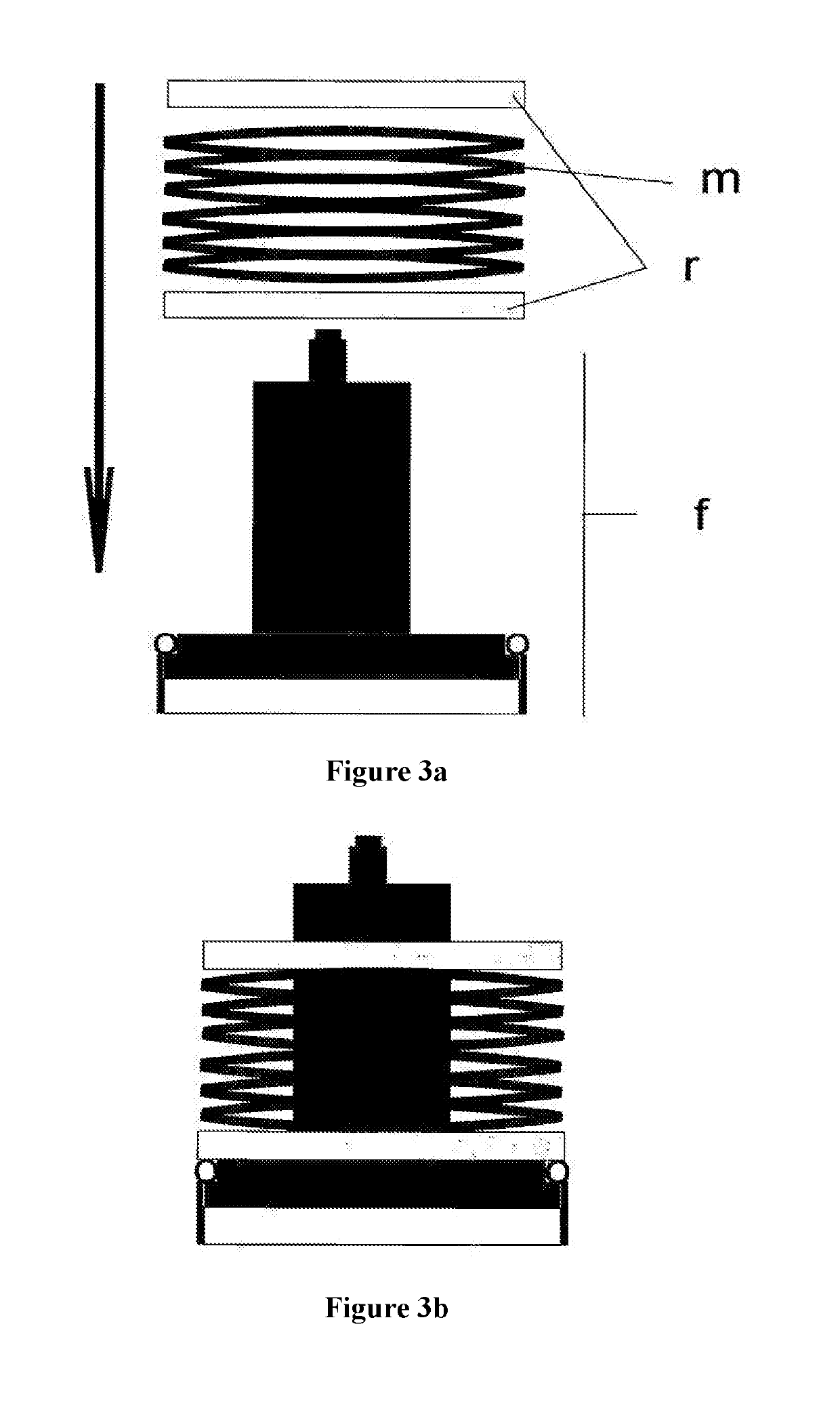
[0043]The column inlet of this new invention consists of the following parts: a column stamp (f) with frit (g) and seals (h), the springs (m), the spring retaining rings (r), a flange pull ring (d), the two column cover halves (b) and the flange screws (c).

[0044]The column cover halves are shown in FIG. 4 in plan view (4a) and in cross-section (4b). The half-shells are shown in FIG. 2(i) in plan view and in longitudinal section.

[0045]Located between the two column cover halves (b) and the column stamp (f) are the springs, delimited at the top and bottom by a spring retaining ring (r). In addition, variously many half-shells (i) can be used for bridging between column cover halves (b) and upper spring retaining ring.

[0046]The column cover halves contain an inner opening (e) for the push rod of the packing apparatus (s) which p...


PUM


Abstract

A separating column for use with a filling tube to prepare for chromatography is disclosed. The separating column includes an axially movable spring stamp; and a plurality of springs coupled to the stamp. Moreover, the stamp is depressed directly into the column tube during column packing via the filling tube. Additionally, the stamp is fixed in the column tube while maintaining the packing pressure so that the springs are compressed during the packing process and press the stamp permanently and dynamically onto a chromatographic bed.

Description

CROSS-REFERENCE TO RELATED APPLICATION[0001]This is a U.S. National application under 35 U.S.C. § 111(a) claiming priority to German Utility Model No. DE 20 2018 001 788.4, filed Apr. 9, 2018, the entire contents of which are hereby incorporated by reference.TECHNICAL FIELD[0002]In liquid chromatography (liquid chromatography, LC, high-pressure liquid chromatography, HPLC) columns made of steel, glass or plastic, packed with special powders are used.BACKGROUND[0003]A standard LC column consists of a stable tube which contains the powdery packing and is closed at both ends with a cover having an opening, a porous frit and a seal. In larger columns a flow distributor can also be incorporated.[0004]LC columns are used to analyze and purify chemical, pharmaceutical substances: in principle all substances which are soluble in water can be analyzed.[0005]In preparative LC an attempt is made to purify fairly large quantities of raw substances in order to use these subsequently, for example...

Claims


Application Information

Patent Timeline
IPC IPC(8): G01N30/22B01D15/20B01D15/22G01N30/56G01N30/60
CPCG01N30/56B01D15/22G01N30/60B01D15/206G01N2030/562G01N30/22G01N30/6004
Inventor MAISCH, ALBIN
Owner ALBIN MAISCH HIGH PERFORMANCE LC
Learn More