Antenna module

a technology of antenna module and antenna body, applied in the direction of antenna details, elongated active element feed, antenna, etc., can solve the problems of inability to obtain desired properties of antenna, inability to accurately control the thickness to 1 [mm] or less, and inability to achieve sufficient strength, simplify and reduce the formation of antenna body, the effect of improving reliability

Active Publication Date: 2019-10-17
MOLEX INC
View PDF3 Cites 2 Cited by
  • Summary
  • Abstract
  • Description
  • Claims
  • Application Information

AI Technical Summary

Benefits of technology

[0010]An object of the present disclosure is to solve the problems of the conventional antenna module, and to simplify conformation and reduce size, to have sufficient strength, and to achieve the desired antenna properties and improved reliability.
[0016]According to the present disclosure, the conformation of the antenna can be simplified and downsized, and the antenna can have sufficient strength, and can exert the desired antenna properties and improved reliability.

Problems solved by technology

However, in the conventional antenna module, the distance between the conductive pattern 851 formed on the outer surface of the cover 811 and the conductive film for shield formed on the antenna device 821 and the inner surface of the cover 811 is difficult to set to be a certain value, and then an antenna having desired properties cannot be obtained.
If the thickness of the cover 811 formed by ceramics or resins becomes thin, the cover cannot have the sufficient strength.
Further, accurately controlling the thickness to 1 [mm] or less is difficult.

Method used


Image

  • Antenna module
  • Antenna module
  • Antenna module

Examples


Embodiment Construction

[0024]An embodiment will be described in detail below with reference to the drawings.

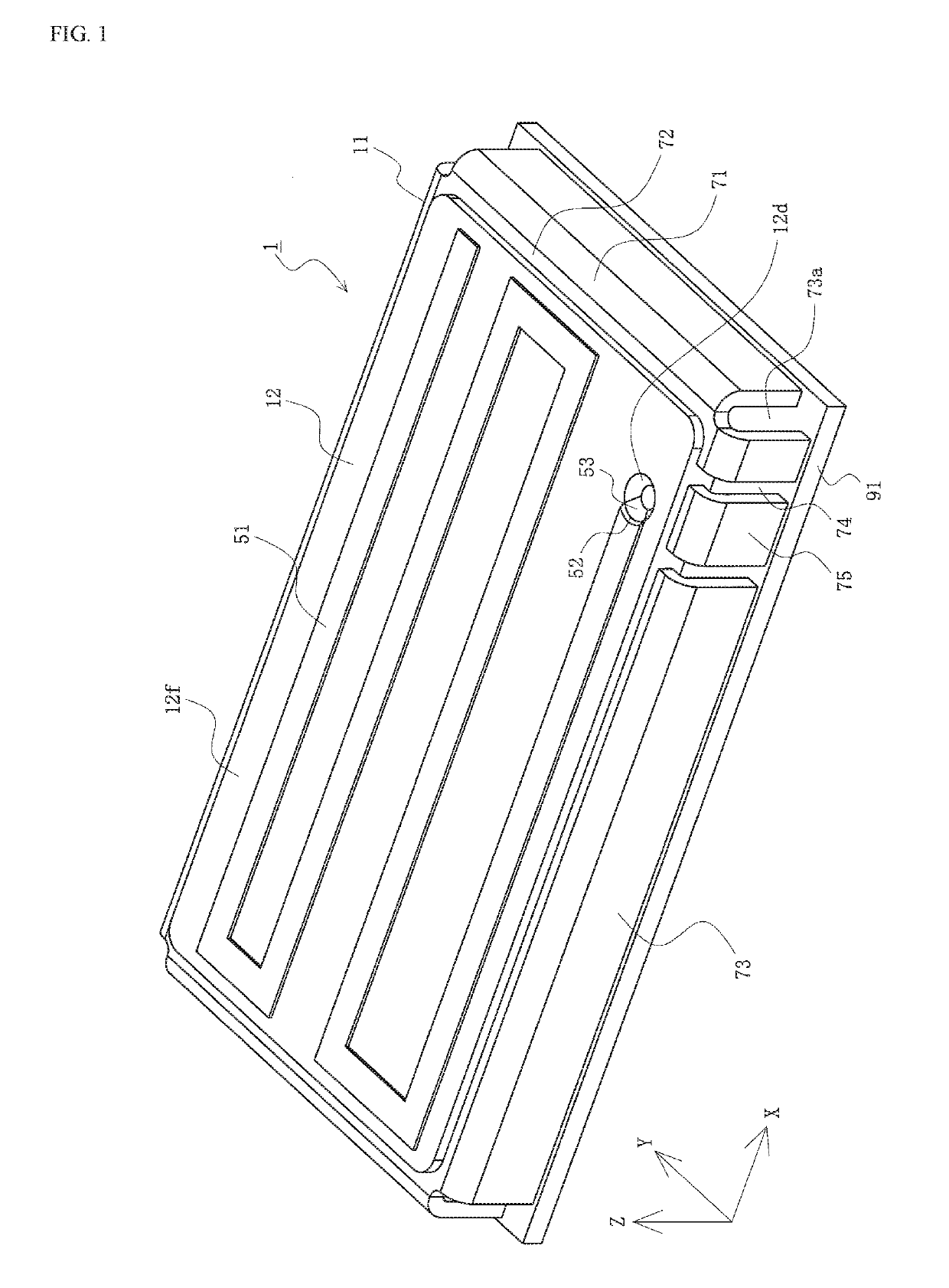
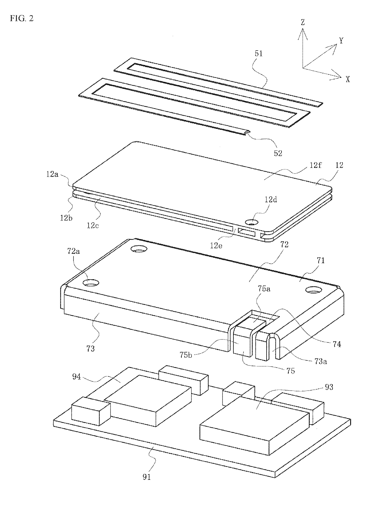
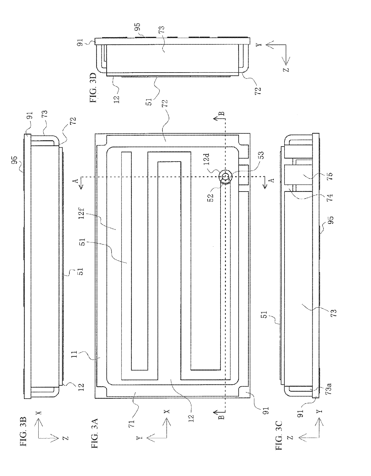
[0025]FIG. 1 is a perspective view of an antenna module in accordance with the first embodiment of the present disclosure. FIG. 2 is an exploded view of the antenna module in accordance with the first embodiment of the present disclosure. FIGS. 3A-3D are four-view drawings of the antenna module in accordance with the first embodiment of the present disclosure, where FIG. 3A is a top view, FIG. 3B is a rear view, FIG. 3C is a front view, and FIG. 3D is a side view. FIGS. 4A and 4B are cross-sectional views of the antenna module in accordance with the first embodiment of the present disclosure, where FIG. 4A is a cross-sectional view of the antenna module taken along the line A-A of FIG. 3A and FIG. 4B is a cross-sectional view of the antenna module taken along the line B-B of FIG. 3A.

[0026]In the Figs., the reference number 1 is an antenna module of this embodiment. The antenna module is a module for...


PUM


Abstract

The antenna module comprises a communication circuit for processing a radio signal; a shield member covering the communication circuit; a conductive strip electrically connected with the communication circuit; a dielectric integrated with the shield member and the conductive strip; and an antenna formed on an outer surface of the dielectric and electrically connected with the conductive strip.

Description

RELATED APPLICATIONS[0001]This application claims priority to Japanese Application No. 2018-077703, filed on Apr. 13, 2018, which is incorporated herein by reference in its entirety.TECHNICAL FIELD[0002]The present disclosure relates to an antenna module.BACKGROUND ART[0003]Conventionally, proposed is a technology for placing on a cover having an antenna formed on the upper surface as an antenna module comprising an antenna for transmitting and receiving a radio signal via a wireless communication, the cover being a box-shaped cover which covers over a communication circuit device mounted on a circuit board (see, for example, Patent Document 1). By the technology, a compact antenna module having a small space required to be mounted can be provided for various electrical equipment and electronic equipment.[0004]FIG. 7 is an exploded view of one conventional antenna module.[0005]In the figure, the reference number 893 is one or plurality of communication circuit device(s) mounted on a...

Claims


Application Information

Patent Timeline
Patent Type & Authority Applications(United States)
IPC IPC(8): H01Q1/38
CPCH01Q1/2291H01Q1/38H01Q9/0407H01Q9/42
Inventor SATO, SHUICHI
Owner MOLEX INC
Why Eureka
Try Eureka