
Fluid dispensing apparatus including phased valves and methods of dispensing fluid using same

a technology of fluid dispensing apparatus and phased valve, which is applied in the direction of transportation and packaging, agriculture tools and machines, relays, etc., can solve the problems of large instantaneous power draw on the electrical system, rapid pressure drop or spike, and uneven fluid flow through the distribution condui

Active Publication Date: 2019-10-24
CAPSTAN
View PDF0 Cites 12 Cited by
  • Summary
  • Abstract
  • Description
  • Claims
  • Application Information

AI Technical Summary

Benefits of technology

The patent describes a method and apparatus for controlling valves in a fluid dispensing apparatus. The valves are connected to a distribution conduit and can be actuated to regulate fluid flow. The method includes determining a phase offset to separate actuation of the valves and a sub-phase offset to separate actuation of valves within a sub-set. The valves are then sequentially actuated based on the phase offset and the sub-phase offset. The technical effect of this invention is improved control of the valves in the fluid dispensing apparatus, allowing for more precise and accurate fluid flow control.

Problems solved by technology

However, the actuation of the valves between an opened position and a closed position may cause uneven fluid flow through the distribution conduit, e.g., the liquid sloshes within the distribution conduit.
In addition, opening or closing multiple valves at the same time may cause rapid pressure drops or spikes within the distribution conduit.
Moreover, opening multiple valves at the same time may result in a large instantaneous power draw on the electrical system.
However, uneven fluid flow, pressure spikes, and current spikes may still occur because the valves in each phase are actuated at the same time.
Accordingly, current valve phasing techniques may be less than optimal for certain applications.

Method used


Image

  • Fluid dispensing apparatus including phased valves and methods of dispensing fluid using same
  • Fluid dispensing apparatus including phased valves and methods of dispensing fluid using same
  • Fluid dispensing apparatus including phased valves and methods of dispensing fluid using same

Examples


Embodiment Construction

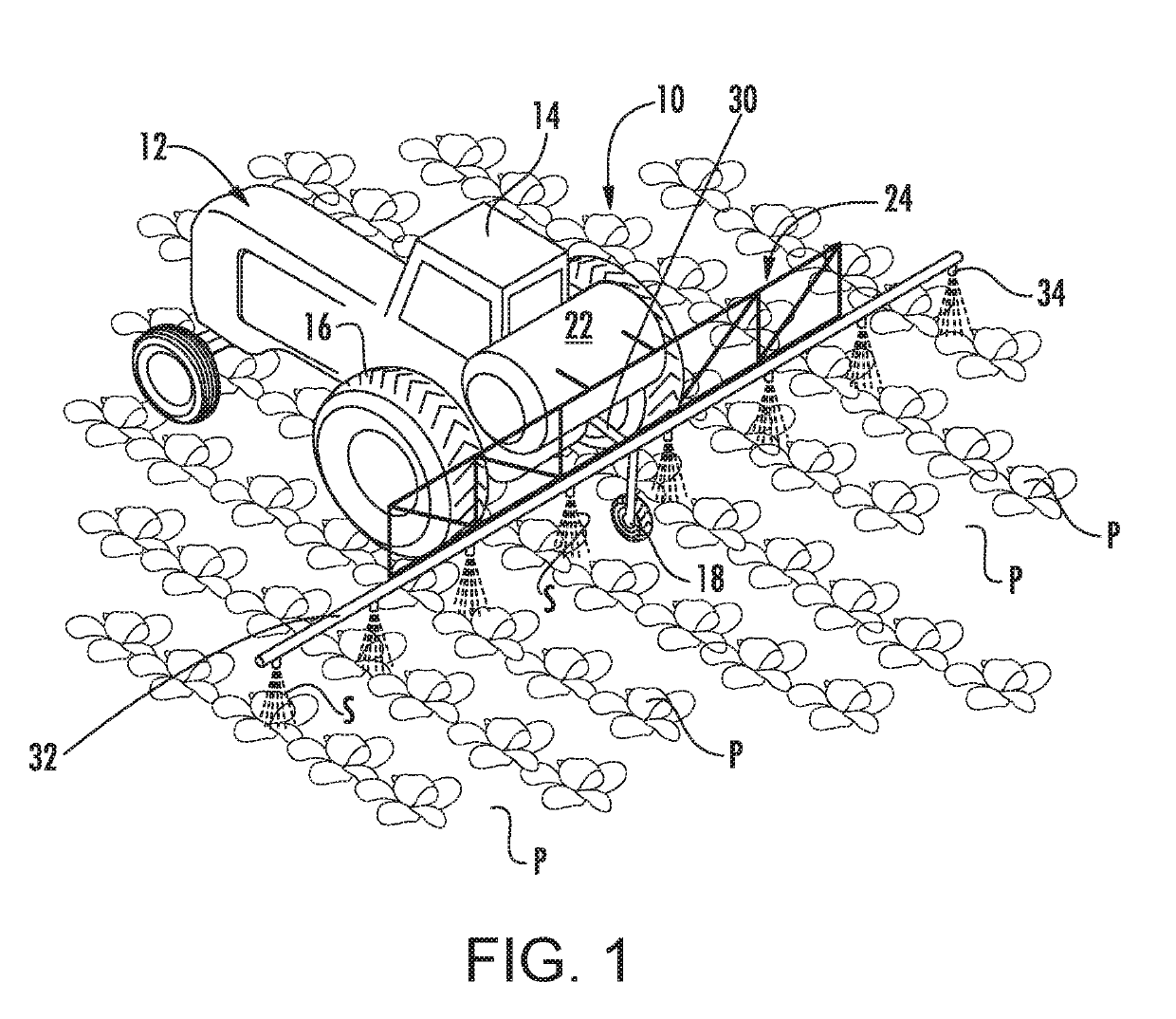
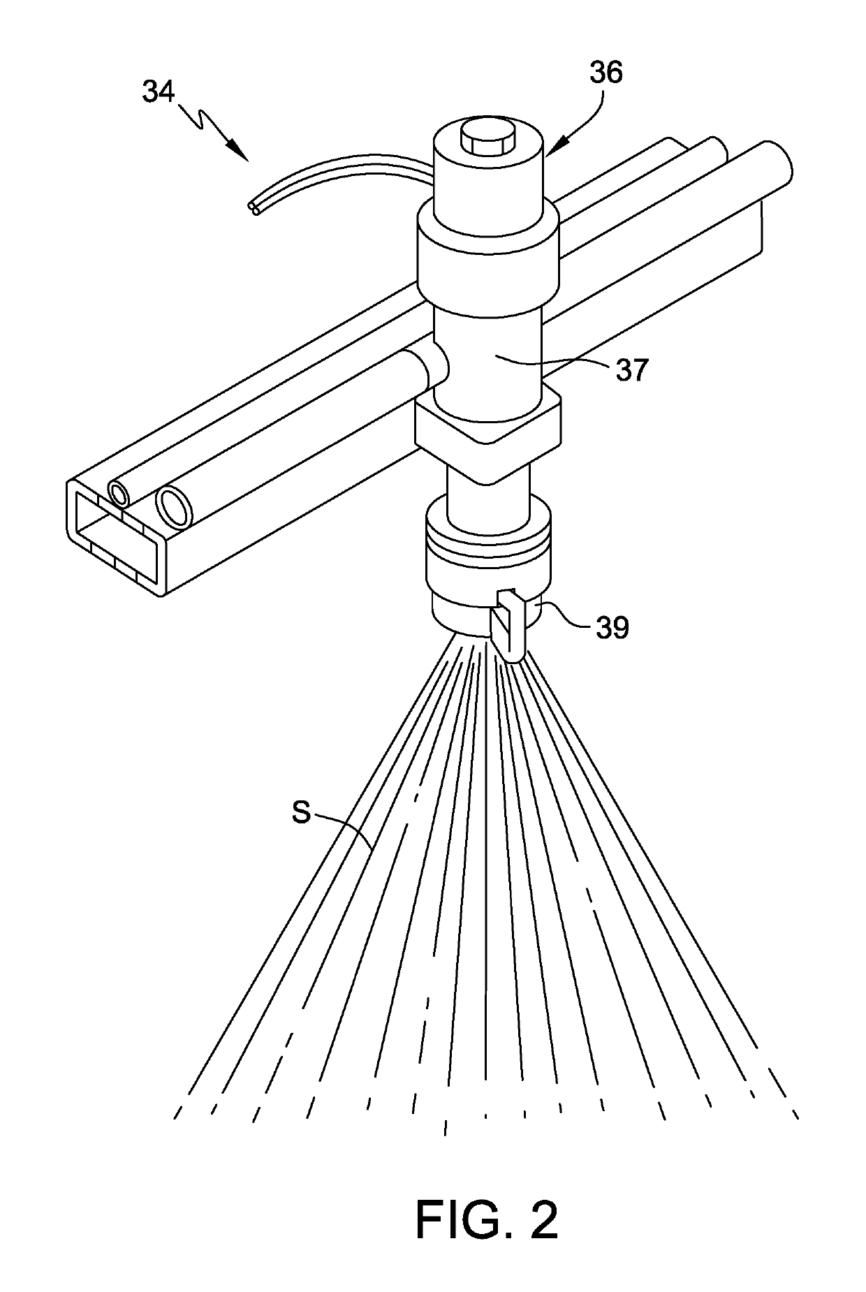
[0031]Referring now to the figures, FIG. 1 is a perspective view of an example fluid dispensing apparatus, indicated generally at 10, operatively connected to a work vehicle 12. As shown, work vehicle 12 includes a cab 14 and a plurality of wheels 16. Work vehicle 12 may, in certain embodiments, be an agricultural tractor having any suitable configuration. However, it should be appreciated that in other embodiments, any other suitable aero or ground vehicle or means may be provided for moving fluid dispensing apparatus 10. For example, in other embodiments, work vehicle 12 may not include a cab, and instead may have any suitable operator station. Further, in some embodiments, work vehicle 12 and / or fluid dispensing apparatus 10 may include a global positioning system (e.g., a GPS receiver) for automated control of work vehicle 12 and / or fluid dispensing apparatus 10. In some embodiments, the global positioning system is used to monitor a travel speed of vehicle 12 and / or fluid dispe...


PUM


Abstract

A method of dispensing fluid from an apparatus includes determining a phase offset to separate actuation of a plurality of valve sub-sets into phases and determining a sub-phase offset to separate actuation of valves within each of the plurality of valve sub-sets. The method also includes sequentially actuating valves in a first sub-set based on the sub-phase offset, and sequentially actuating valves in a second sub-set based on the phase offset and the sub-phase offset such that (i) at least one valve in the second sub-set is actuated out of phase from a preceding valve in the first sub-set by the phase offset; and (ii) the at least one valve in the second sub-set is actuated out of phase from a preceding valve in the second sub-set by the sub-phase offset.

Description

CROSS-REFERENCE TO RELATED APPLICATIONS[0001]This application claims priority to U.S. Provisional Patent Application Ser. No. 62 / 661,344, filed on Apr. 23, 2018, the disclosure of which is hereby incorporated by reference in its entirety.BACKGROUND[0002]The present disclosure relates generally to apparatus and methods for dispensing fluid and, more particularly, to fluid dispensing apparatus and methods using phased valves to control the emission of fluid through fluid dispensing apparatus.[0003]In the agricultural industry, fluid dispensing apparatus are used to dispense agrochemicals. For example, some agrochemicals such as crop protection agents and many fertilizers are applied as liquid solutions, suspensions, and emulsions that are sprayed onto the target fields. Certain agrochemicals, such as anhydrous ammonia, are dispensed into soil through dispensing tubes positioned behind knives or plows that prepare the soil for application.[0004]Typically, the agrochemical liquid is sup...

Claims


Application Information

Patent Timeline
Patent Type & Authority Applications(United States)
IPC IPC(8): B05B12/00A01B79/02B05B1/30A01B79/00
CPCB05B12/004B05B1/30A01B79/005A01B79/02B05B1/20B05B1/3053B05B12/04H01F7/064A01M7/0089Y10T137/7761B05B12/00H01H47/04
Inventor SCHRADER, KALENEEDHAM, DUANE
Owner CAPSTAN
Learn More