Spark discharge ignition promoting method, spark discharge ignition promoting apparatus, and engine with spark discharge ignition promoting apparatus

a technology of spark discharge ignition and spark discharge, which is applied in the direction of machines/engines, sparking plugs, automatic control of ignition, etc., can solve the problems of unstable combustion, deterioration of fuel efficiency, and inability to exert intended output, so as to ensure and stably ignite, the life of the apparatus is longer, and the energy saving effect of ignition

Inactive Publication Date: 2019-10-24
NAT INST OF ADVANCED IND SCI & TECH
View PDF6 Cites 0 Cited by
  • Summary
  • Abstract
  • Description
  • Claims
  • Application Information

AI Technical Summary

Benefits of technology

[0023]It is thus an object of the present invention to provide a spark discharge ignition promoting apparatus, an engine with the spark discharge ignition promoting apparatus, and a spark discharge ignition promote method capable of surely and stably igniting, making energy saving in ignition, making a life of the apparatus longer, and realizing the apparatus at low cost and with relatively compact size, in order to realize an engine, which operates even in a lean or super-lean air-fuel mixture, in a premixing combustion method.
[0048](3) It is possible to make a life of the apparatus longer.
[0049](4) It is possible to realize the apparatus at low cost.

Problems solved by technology

However, in a case where the air-fuel ratio is made super lean or super dilution is carried out by recirculating a large amount of exhaust gas to a combustion chamber, there has been a problem that combustion becomes unstable and not only an intended output cannot be exerted, but also fuel efficiency is deteriorated due to misfire.
The ignition by the spark plug, which is conventional igniting means becomes unstable in a case where a lean / dilution air-fuel mixture is used.
Thus, it is hard to ignite.
Namely, a problem that the engine cannot be operated by the air-fuel mixture in a lean / dilution region occurs.
However, even though the recirculation exhaust is distributed at the thick air-fuel mixture portion in the center of the combustion chamber or the stratified mixture is guided to the vicinity of the spark plug, there is a limit to make the air-fuel mixture lean and an operational region in which lean air-fuel mixture is available is also limited.
Even though the ignition method by only non-thermal plasma can cause an engine to operate by using a lean / dilution air-fuel mixture, supplied electric power is large by applying high voltage.
For this reason, an electrode of the means for generating the plasma is susceptible to be damaged, and there has been a problem that a life of the electrode is short.
Further, generation efficiency of radicals is poor, and electric power consumption is large.
Since a large power source is required for formation of voluminous plasma, there has been a problem that the whole apparatus provided with the generating means for generating the plasma becomes large.
However, it is different from the non-thermal plasma ignition described above.
There is a drawback that a precise control for ignition timing is difficult in the HCCI engine.
However, there is no effect of the ignition for a lean air-fuel mixture unless the partial oxides and the like with a prescribed concentration are contained therein.
However, the air-fuel mixture containing the partial oxides and the like are mixed and diffused due to sucking to the spark plug and a concentration of the partial oxides becomes diluted, whereby ease of ignition against lean air-fuel mixture ignition cannot be obtained.
In order to do so, there is a problem that energy consumption must become large and generating means for generating plasma must also become large.
Moreover, by subjecting almost all of the air-fuel mixture to non-thermal plasma treatment, abnormal ignition readily occurs.
To the contrary, there is concern that knocking occurs.
As described above, there have been many problems to realize a lean / dilution or super lean / super dilution combustion engine by the prior art.
For example, as described above, in the method disclosed in Japanese Patent Application No. 2015-542682, it was found that it is actually difficult to avoid diffusion of a premixed fuel processed by formation of non-thermal plasma in a conventional intake pipe and cause the premixed fuel to concentrate in the vicinity of a spark plug by means of a flow after an intake valve is closed.
If it does not become appropriate temperature and an appropriate pressure state, an easy combustion characteristic is lost.
Properties of the air-fuel mixture in the easy combustion region are actually lost even due to an air flow by means of mixing, diffusion or the like when it is sent together with a normal air-fuel mixture, whereby it does not lead to stable combustion.
Namely, it is difficult to operate the lean or super lean engine described above by mere combination of the non-thermal plasma and the spark plug.

Method used


Image

  • Spark discharge ignition promoting method, spark discharge ignition promoting apparatus, and engine with spark discharge ignition promoting apparatus
  • Spark discharge ignition promoting method, spark discharge ignition promoting apparatus, and engine with spark discharge ignition promoting apparatus
  • Spark discharge ignition promoting method, spark discharge ignition promoting apparatus, and engine with spark discharge ignition promoting apparatus

Examples


first embodiment

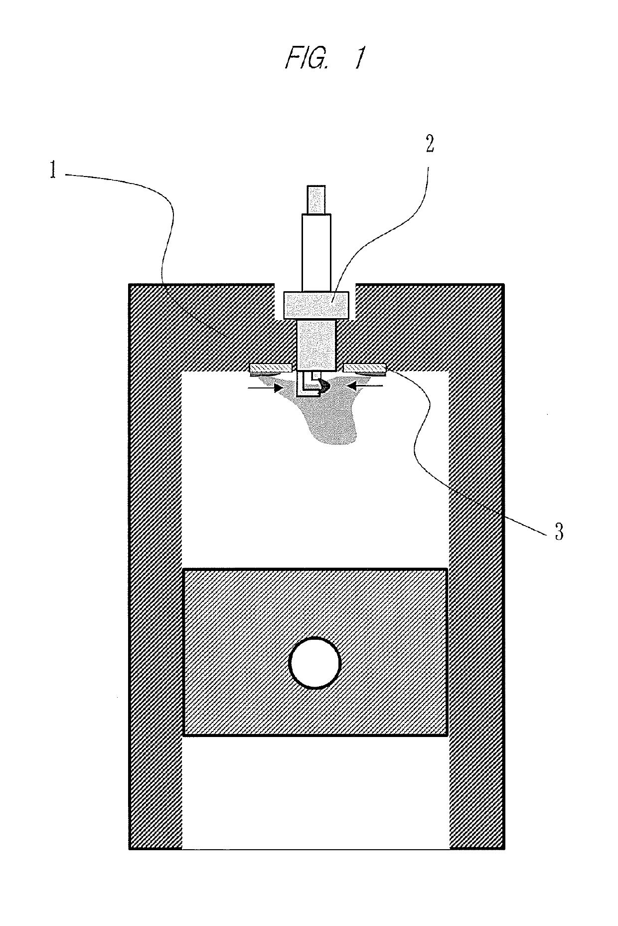
[0074]FIG. 1 shows the whole configuration according to the first embodiment. A spark plug 2 is mounted on a cylinder head 1. An ignition promoting apparatus 3 is installed around the spark plug 2. The ignition promoting apparatus 3 is configured to generate an induced flow with discharge of non-thermal plasma. In the first embodiment, an electrode of non-thermal plasma generating means is provided along a surface of the inside of a cylinder. Therefore, it is a configuration in which a size of an area in which the non-thermal plasma is generated is flexibly set and easily installed on the cylinder surface.

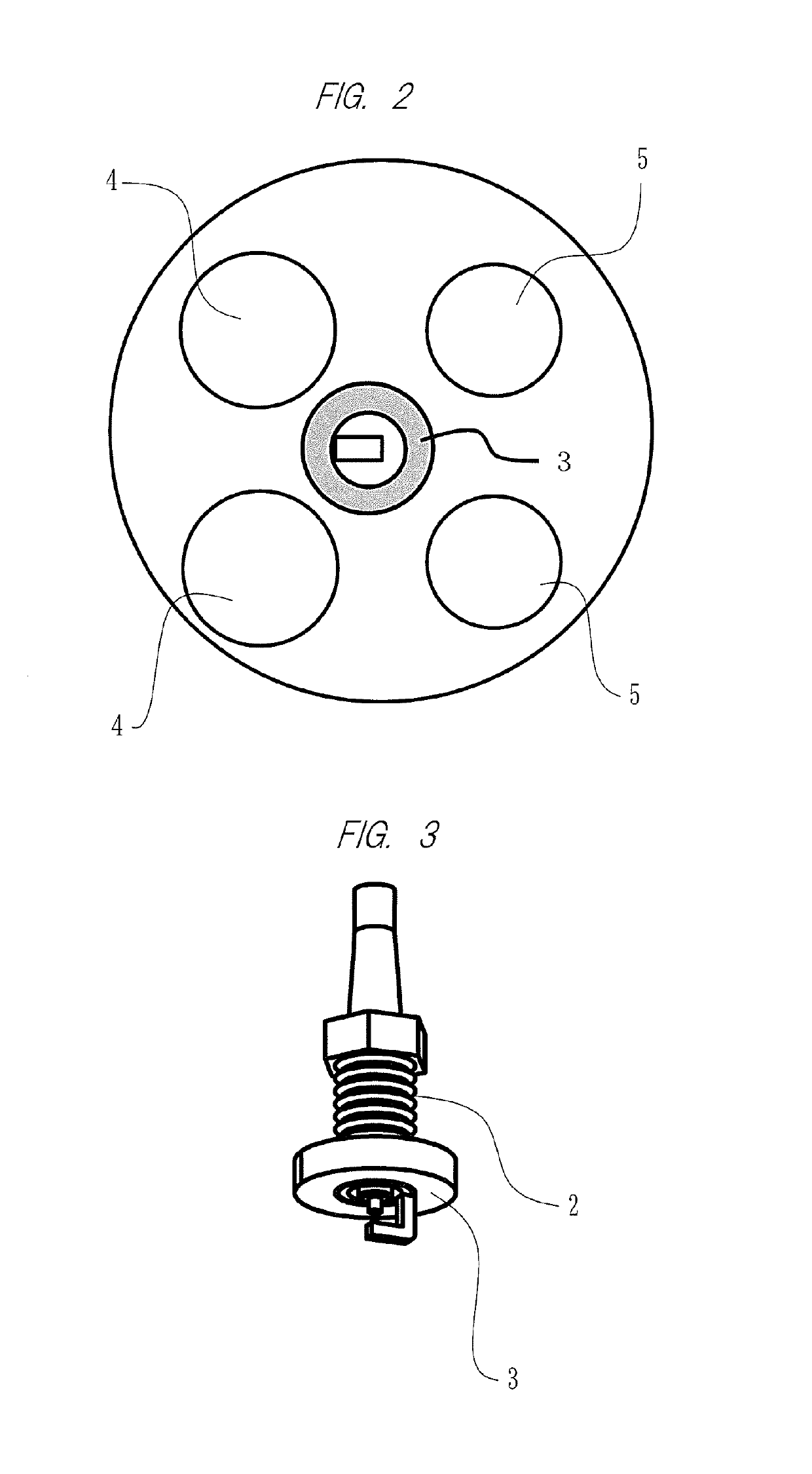
[0075]FIG. 2 is a view of the cylinder head 1 when viewed from a combustion chamber side. In the present embodiment, the spark plug 2 is arranged at a central portion that is encircled by intake valves 4 and exhaust valves 5.

[0076]In this regard, a fuel supplying method may be either a port injection method or a direct injection method.

[0077]FIG. 3 shows a relationship between the ...

second embodiment

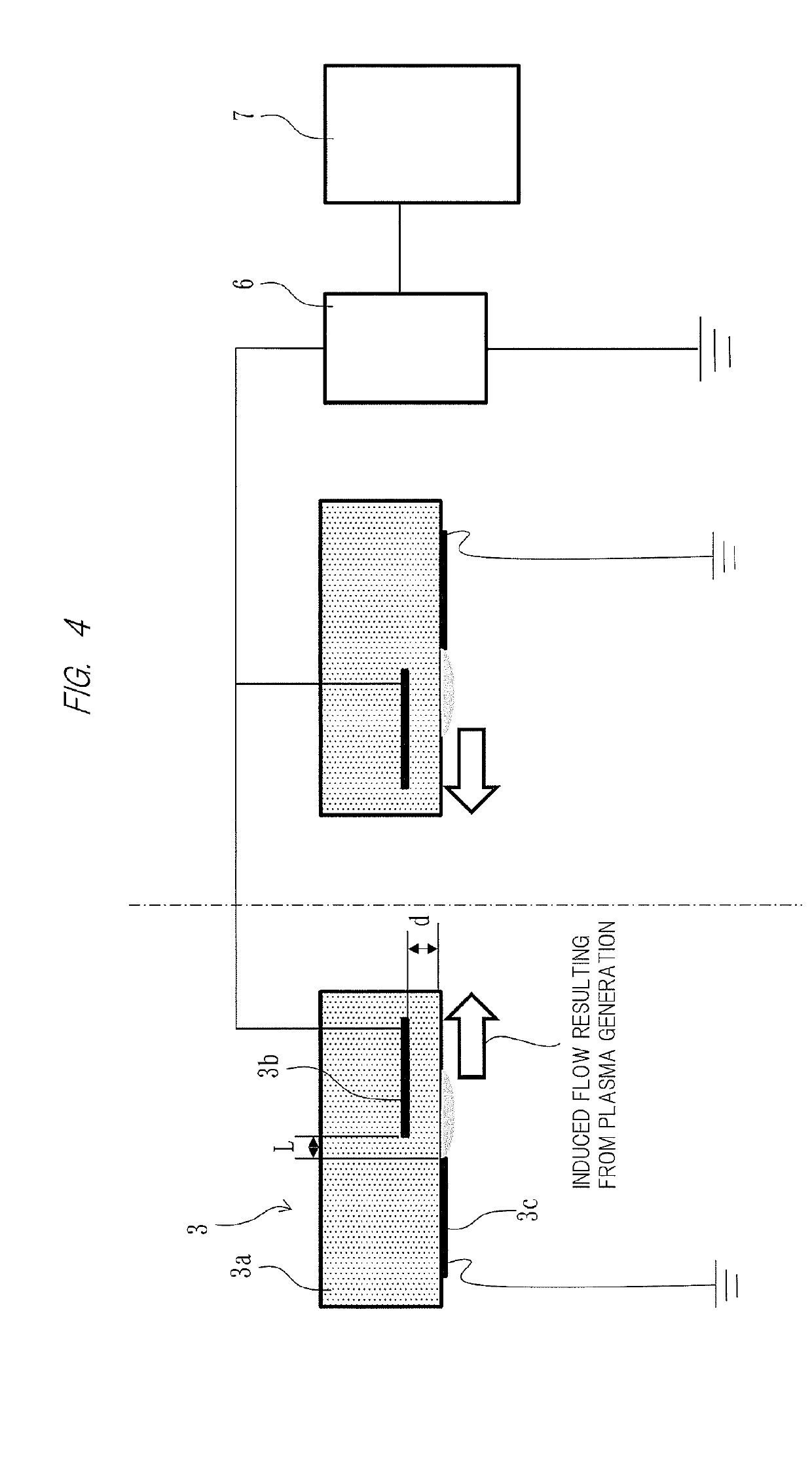
[0098]FIG. 5 shows a configuration of a second embodiment. In the second embodiment, by embedding an annular embedded electrode 3b in an insulator through which a central electrode of a spark plug 1 goes and fitting the annular exposed electrode 3c to an outer surface of the insulator, an induced flow resulting from plasma generation is injected toward the inside of a combustion chamber from a space formed between an outer circumference of the insulator and the grounded electrode.

[0099]In order to gain a ratio of a thermal plasma generating area in the cylinder, it is necessary to thicken and / or lengthen an electrically insulating tube member integrated with a plug around the plug, which is made of ceramic. However, installation to an engine cylinder is substantially similar to that of a conventional spark plug. It is easy to install and exchange it, and it is a configuration easy for maintenance.

[0100]As described above, the invention made by the inventors of the present applicatio...


PUM


Abstract

Stable combustion becomes possible even in a super-lean combustion engine or an engine that carries out a large amount of EGR. In a spark discharge ignition promoting apparatus, non-thermal plasma is generated in a cylinder by a non-thermal plasma generating unit. The non-thermal plasma generating unit is provided at a location where a processed air-fuel mixture by the non-thermal plasma reaches a spark plug after an in-cylinder flow or where the air-fuel mixture exists around an electrode of the spark plug in a time when the air-fuel mixture keeps an easy combustion state. The spark plug ignites the processed air-fuel mixture by discharge of the spark plug at timing when the processed air-fuel mixture by the non-thermal plasma of an easy combustion state reaches the spark plug after an in-cylinder flow or timing when the air-fuel mixture of the easy combustion state exists around an electrode of the spark plug in the time when the air-fuel mixture keeps the easy combustion state.

Description

CROSS-REFERENCE TO RELATED APPLICATIONS[0001]This application is a National Stage application of International Patent Application No. PCT / JP2016 / 083246, filed on Nov. 9, 2016, which claims priority to Japanese Patent Application No. 2015-219289, filed on Nov. 9, 2015, each of which is hereby incorporated by reference in its entirety.TECHNICAL FIELD[0002]The present invention relates to a spark discharge ignition promoting method, a spark discharge ignition promoting apparatus, and an engine with the spark discharge ignition promoting apparatus. More particularly, the present invention relates to a technique effective for a super lean combustion engine or promotion of spark discharge ignition in an engine that carries out a large amount of EGR.BACKGROUND ART[0003]In recent years, improvement of fuel efficiency of an engine, which includes a gasoline engine for a vehicle, in a premixing combustion method has become the strongest theme. It is effective to reduce pumping loss as much as...

Claims


Application Information

Patent Timeline
Patent Type & Authority Applications(United States)
IPC IPC(8): F02P5/15F02P3/01F02B23/08F02P15/02F02P15/10F02P9/00
CPCF02P3/01F02P15/10F02P9/007F02P5/15H01T13/22F02B23/08F02P15/02F02P9/00H01T13/46H01T13/50F02P3/04F02P23/045
Inventor TAKAHASHI, EIICHISEGAWA, TAKEHIKO
Owner NAT INST OF ADVANCED IND SCI & TECH
Why Eureka
Try Eureka