Photovoltaic module

Inactive Publication Date: 2019-10-24
BENEDETTI FEDERICA
View PDF0 Cites 0 Cited by
  • Summary
  • Abstract
  • Description
  • Claims
  • Application Information

AI Technical Summary

Benefits of technology

[0027]In any case, the greater the thickness of the encapsulating material, the greater is also the overall cost of the module and its lamination process, becaus

Problems solved by technology

The photovoltaic modules described in the prior art, including those of the above-mentioned documents, suffer from certain drawbacks.
Consequently, the technology according to the patent US2009250093 has a limitation in the economic savings which can be obtained with the use of these mirror surfaces.
Moreover, the photovoltaic modules described in patent document EP 1732141 do not allow the use of front and rear sheets of the casing which have flat inner surfaces.
This means that micro fissures or fractures are created from the start of the assembly inside the cell, which often over time result in the complete breakage of the photovoltaic cell into various fragments.
Thus, the micro fissures caused by the above-mentioned edges lead to the reduction of the average life cycle of the photovoltaic cells.
Moreover, the interconnecting elements between the photovoltaic cells are also subjected, in use, to thermal expansion; this thermal expansion is well known to cause faults in the photovoltaic panels, and in particular it may cause slight deformations.
More specifically, the presence of the cavity in the triangular grooves reduces the reliability of lamination of the photovoltaic module, as it hinders the removal of the air between the plates, causing the permanence of possible bubbles also after the lamination has ended.
This, in particular, may occur due both to the inability of the encapsulating material to occupy the entire space of the cavities, as

Method used


Image

  • Photovoltaic module
  • Photovoltaic module
  • Photovoltaic module

Examples


first embodiment

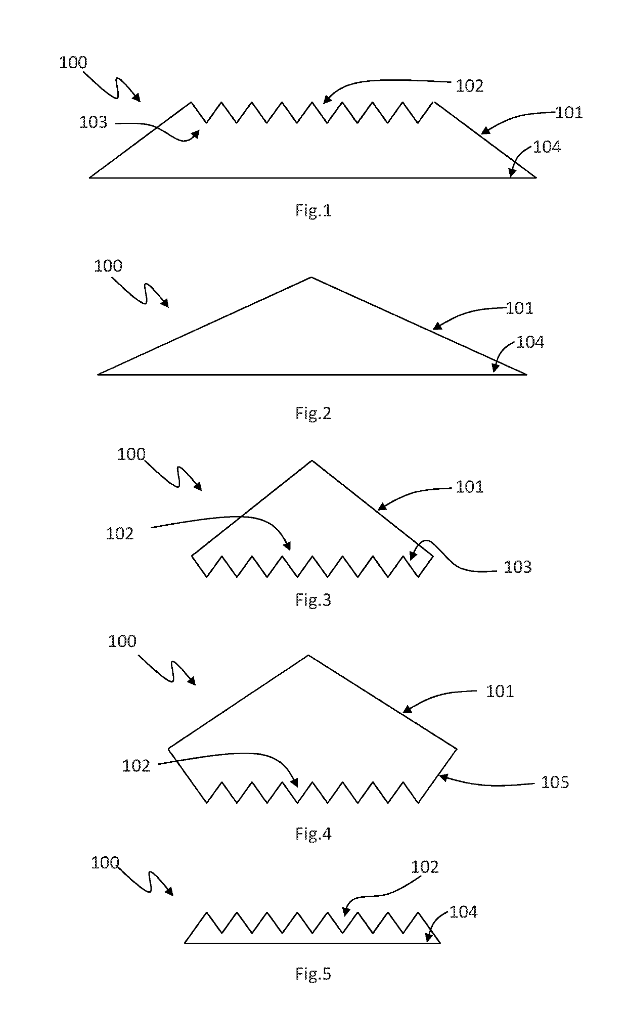
[0054]In the first embodiment illustrated in FIG. 1, the solar deflector 100 comprises a first pair of reflective surfaces 101 oriented in opposite directions to each other, between which there is interposed a sequence 102 of reflective surfaces 103 positioned in the form of a triangle.

[0055]Substantially, the sequence 102 of reflective surfaces 103 extends along a direction of maximum extension at right angles to the direction which is identified by the thickness of the photovoltaic panel, and also comprises a sequence of reflective surfaces 103 joined at one end of them alternatively upper and lower and oriented to each other in opposite directions and symmetrical about an axis at right angles to the direction of maximum extension identified by them, without interposing further walls between them, namely parallel to the direction of maximum extension, thus being in direct connection.

[0056]It should also be noted that although the accompanying drawings illustrate reflective surface...

third embodiment

[0067]In the deflector 100 according to this invention, illustrated in FIG. 3, in a similar fashion to the embodiment illustrated in FIG. 2, the reflective surfaces 101 are oriented in the opposite directions to each other, and each has a first end joined with the first end of the other reflective surface 101 so as to form an angle at the top which is convex and a second end which, on the other hand, is joined with a sequence 102 of reflective surfaces 103 which thus lie at a height lower and which correspond in use to the rear face of the photovoltaic module.

[0068]A fourth embodiment of the deflector 100 according to the invention is illustrated in FIG. 4. The fourth embodiment is similar to the third embodiment described above. The fourth embodiment also has reflective surfaces 101 which are oriented in the opposite directions to each other, and each has a first end joined with the first end of the other reflective surface 101 so as to form an angle at the top which is convex and ...

fourth embodiment

[0069]The third and fourth embodiment described above each have the presence of reflective surfaces on both the front and rear faces; this feature is important since these collectors are designed for a use inside a two-faced photovoltaic module, that is to say, characterised by cells which are able to collect the solar radiation on both faces and having front and rear covering plates which are both transparent.


PUM


Abstract

Photovoltaic module (200) comprising at least one photovoltaic cell (201), at least one electrical interconnecting connection (206, 204) and at least one solar deflector (100) the solar deflector (100) comprising a groove for containing at least the one electrical interconnecting connection (206, 204) or the photovoltaic cell (201), the groove having a main direction of extension and comprising at least bilateral containment means of the electrical interconnecting connection (206, 204) or the photovoltaic cell (201) along a direction transversal to the main direction of extension.

Description

TECHNICAL FIELD[0001]This invention relates in general to the field of solar collection technologies and in detail relates to a photovoltaic module.BACKGROUND ART[0002]There are prior art devices comprising photovoltaic modules with concentrators having reflective surfaces—formed by a mirror—having grooves with a V-shaped profile placed alongside each other. This type of photovoltaic modules is known in the jargon of the trade with the term ‘V-grooved’.[0003]Alongside the grooves with a V-shaped profile may be placed flat reflective surfaces—or flat mirrors—inclined with a direction opposite to that of the V-shaped grooves.[0004]These flat reflective surfaces may also be, if necessary, joined together uninterruptedly, thus forming a set of surfaces forming a system for collecting the electromagnetic solar radiation, which is diverted towards the sides of the system itself where photovoltaic cells are positioned that are designed for converting the solar radiation received into elect...

Claims


Application Information

Patent Timeline
IPC IPC(8): H01L31/054H01L31/05H01L31/048
CPCH01L31/0547H01L31/0488H01L31/0504H01L31/048Y02E10/52H02S40/22
Inventor FALSINI, MARTINO
Owner BENEDETTI FEDERICA
Why Eureka
Try Eureka