Piston pin and method of applying an anti-seize coating on the pin

Active Publication Date: 2018-11-13
H E F +1
View PDF15 Cites 0 Cited by
  • Summary
  • Abstract
  • Description
  • Claims
  • Application Information

AI Technical Summary

Benefits of technology

[0027]It can also be observed that the fact of partially coating the pin enables to envisage the use o

Problems solved by technology

The piston compression height is constrained by such an assembly and does not enable to optimize the piston mass.
On small vehicles, this solution enables to decrease the height under the hood and to thus limit the aerodynamic coefficient, and accordingly aerodynamic losses.
However, th

Method used


Image

  • Piston pin and method of applying an anti-seize coating on the pin
  • Piston pin and method of applying an anti-seize coating on the pin
  • Piston pin and method of applying an anti-seize coating on the pin

Examples


Embodiment Construction

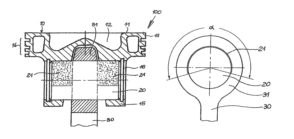
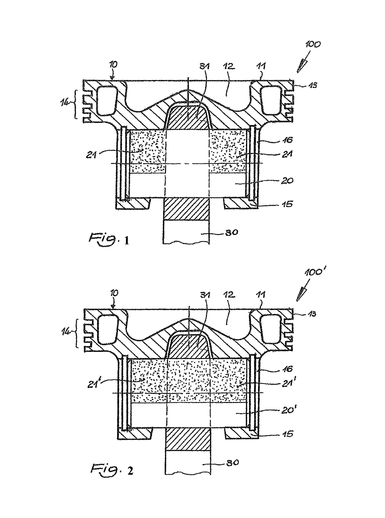
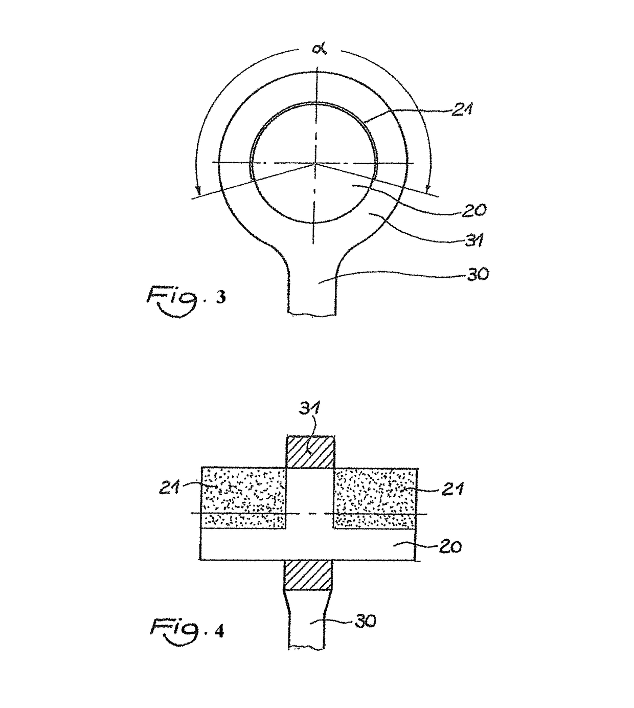
[0068]FIGS. 1, 3, and 4 show an embodiment of a structural unit (100) according to the invention. The structural unit (100) is provided with a piston (10) which may be freely formed as concerns its composition and materials. The piston (10) of the embodiment is a one-piece box-shaped piston with a piston top (11), a combustion cavity (12), a peripheral piston cover (13), and a peripheral piston ring (14). The piston (10) is further provided with conventional piston bosses (15) with boss bores (16) for receiving a piston pin (20). The piston bosses (15) are conventionally connected by bearing surfaces (not shown).

[0069]The structural unit (100) is provided with a connecting rod (30) next to the piston (10) and to the piston pin (20). The connecting rod (30) is provided with a conventional small end (31). The piston pin (20) is fixedly and immovably assembled in the small end (31) of the connecting rod, for example, by binding. This type of connecting rod is also known as a “tight con...


PUM

PropertyMeasurementUnit
Fractionaaaaaaaaaa
Thicknessaaaaaaaaaa
Thicknessaaaaaaaaaa

Abstract

The piston pin has an anti-seize coating limited to an angular sector corresponding at least to a friction area submitted to a contact pressure along a preferential direction.

Description

CROSS REFERENCE TO RELATED APPLICATIONS[0001]This application is a national stage filing under section 371 of International Application No. PCT / EP2014 / 067274, filed on Aug. 12, 2014, and published in English on Mar. 5, 2015, as WO 2015 / 028305 A1 and claims priority of German application no. 10 2013 014 385.3 filed on Aug. 30, 2013 and French application no. 1359324 filed on Sep. 27, 2013, the entire disclosure of these applications being hereby incorporated herein by reference.BACKGROUND ART[0002]The invention relates to the field of tribological contacts, and more generally to any system where a pin is tightly assembled and is submitted to stress along a preferential direction inducing a stress of said pin according to a partial angular sector. The invention advantageously relates to a piston pin.[0003]Two types of piston pin-to-connecting rod connections are currently used:[0004]a) Floating connection[0005]b) Tight connection[0006]A floating connection enables to assemble the pin ...

Claims


Application Information

Patent Timeline
IPC IPC(8): F16J1/16C23C16/50C23C14/06C23C14/00C23C16/27C23C14/02
CPCF16J1/16C23C14/00C23C16/27C23C16/50C23C14/0605C23C14/024C23C14/0641
Inventor HENRY, SANDRINEHEAU, CHRISTOPHEPROST, FABRICELOCHMANN, ROLANDMAURIZI, MARCO
Owner H E F
Why Eureka
Try Eureka