
Transmission, particularly for a wheeled vehicle, and wheeled vehicle equipped with such a transmission

a transmission and wheeled technology, applied in the direction of vehicle sub-unit features, interlocking clutches, gearing, etc., can solve the problems of generating additional cost, affecting the driving experience of the vehicle, and affecting so as to reduce the risk of premature damage, improve the mechanical strength of the transmission, and reduce the cost

Active Publication Date: 2019-10-31
FRANCE REDUCTEURS SA
View PDF4 Cites 10 Cited by
  • Summary
  • Abstract
  • Description
  • Claims
  • Application Information

AI Technical Summary

Benefits of technology

The invention is designed to provide a compact transmission that is stronger and more durable, at a lower cost. It also allows for easy engagement with freewheeling, the use of low-torque motors, and the ability to change the speed of the transmission's output shaft over a wide range. These features make it easier to design and modify vehicles with the transmission, improving their performance and efficiency.

Problems solved by technology

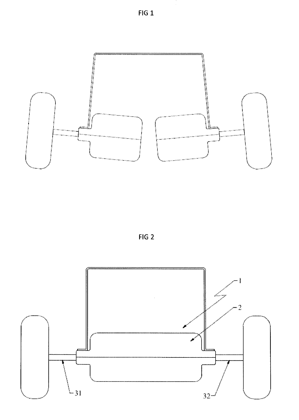
With such an assembly, under the effect of the weight of the chassis of the vehicle, there exists a considerable risk of misalignment between the outlet half-shafts, as shown in FIG. 1.
That misalignment may have damaging consequences for driving the vehicle.
In order to avoid that misalignment, it is necessary to reinforce the bearings and to increase the mechanical strength of the transmission assembly, thus generating additional cost.
That results in bulkiness of the housing and makes it necessary to reinforce the housing in order for the housing to be able to support both the motors and the outlet shaft.
That reinforcement leads to additional cost of the assembly.
This results in increased compactness of the transmission.

Method used


Image

  • Transmission, particularly for a wheeled vehicle, and wheeled vehicle equipped with such a transmission
  • Transmission, particularly for a wheeled vehicle, and wheeled vehicle equipped with such a transmission
  • Transmission, particularly for a wheeled vehicle, and wheeled vehicle equipped with such a transmission

Examples


Embodiment Construction

[0038]As mentioned above, the transmission 1 of the invention is more particularly designed to drive the movement of a wheeled vehicle, such as a snow plough, a mowing tractor, a golf cart, or other vehicle.

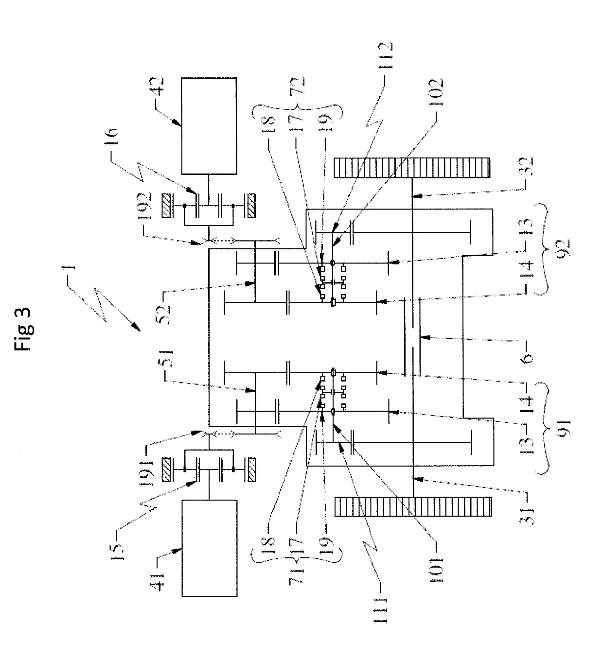
[0039]The transmission 1 comprises a housing 2 defining an enclosure. The housing 2, preferably made of synthetic material, is formed by two half-shells that can be assembled together by bearing contact between the facing surfaces of the two half-shells. The housing 2 is generally filled with a lubricant. The outlet shaft of the transmission, which in this embodiment forms the drive shaft for driving the wheels of a pair of wheels of the vehicle is inserted in part inside the housing. This outlet shaft is formed by a first outlet shaft section 31 and by a second outlet shaft section 32, which sections are connected together in such a manner as to be free to rotate relative to each other via at least one connection part 6 arranged inside the housing 2. The outlet shaft extends in ...


PUM


Abstract

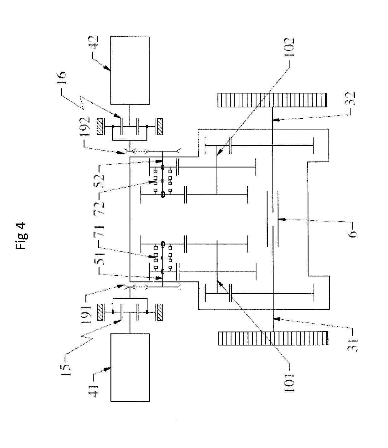
The transmission (1) comprises a housing (2), a first motor (41), a second motor (42), a first and a second input shaft (51, 52), respectively able to be driven in rotation, one (51) by the first motor (41), the other (52) by the second motor (42), two clutch mechanisms (71, 72) and two reduction gears (91, 92), wherein the output shaft (31, 32) is formed by two output shaft sections (31, 32) interconnected such that they rotate freely, the clutch mechanisms (71, 72) are each equipped with a clutch control member operable by a user for allowing the transmission, in the engaged state of the first clutch mechanism (71), of the rotational movement of the first input shaft (51) to the first output shaft section (31), and the transmission, in the engaged state of the second clutch mechanism (72), of the rotational movement of the second input shaft (52) to the second output shaft section (32), and the reduction gears (91, 92) are at least partially received inside the housing (2).

Description

FIELD OF THE INVENTION[0001]The invention relates to a transmission, in particular for a wheeled vehicle, and to a wheeled vehicle fitted with such a transmission.[0002]The invention relates more particularly to a transmission comprising a housing defining an enclosure and an outlet shaft housed at least in part in said housing.PRIOR ART[0003]In general, when a wheeled vehicle is fitted with a transmission for rotating at least one pair of wheels of the vehicle, with each wheel driven independently of the other, the assembly is as shown in FIG. 1, which shows the state of the art. Thus, the shaft for driving the wheels, also referred to as the outlet shaft of the transmission, is formed by two half-shafts, each housed at least in part in a housing. Each housing houses a motor with a drive shaft engaged by meshing directly with the outlet half-shaft for driving a wheel of the vehicle. With such an assembly, under the effect of the weight of the chassis of the vehicle, there exists a ...

Claims


Application Information

Patent Timeline
Patent Type & Authority Applications(United States)
IPC IPC(8): F16H3/091F16H37/04
CPCF16H37/04F16H2063/3093F16H2702/02F16H3/091F16D11/14F16H2200/0034F16H63/30F16H63/04F16H2057/02034B60K7/0007B60K17/043B60K17/046B60K2007/0046B60K2007/0061B60Y2200/15B60Y2200/22B60Y2200/221B60Y2200/23B60Y2410/10B60K1/02B60K17/08F16H3/089F16H37/02F16H2200/0021
Inventor BARENDRECHT, WOUTER
Owner FRANCE REDUCTEURS SA
Learn More