Oil Tank Filling System

a filling system and oil tank technology, applied in the direction of machines/engines, liquid transfer devices, turbines, etc., can solve the problems of unsafe or at least inconvenient access for maintenance engineers, especially in the core engine, and not suitable, or at least not favorable,

Active Publication Date: 2019-11-07
ROLLS ROYCE PLC
View PDF0 Cites 4 Cited by
  • Summary
  • Abstract
  • Description
  • Claims
  • Application Information

AI Technical Summary

Benefits of technology

[0022]The oil access port and the sight viewing glass may be positioned to be outboard of a matrix cooler i.e. to tak

Problems solved by technology

While that method is effective for those engines and many other engines, it is not suitable, or at least not favourable, for engines where broader design reasons require the oil tank to be located within the core engine.
For example, the oil tank may be housed within an engine nacelle and is therefore generally inaccessible to a maintenance engineer with an oil can or it is unsafe or at least inconvenient to be accessed by a maintenance engineer.
These problems are acute when the oil ta

Method used


Image

  • Oil Tank Filling System
  • Oil Tank Filling System
  • Oil Tank Filling System

Examples


Embodiment Construction

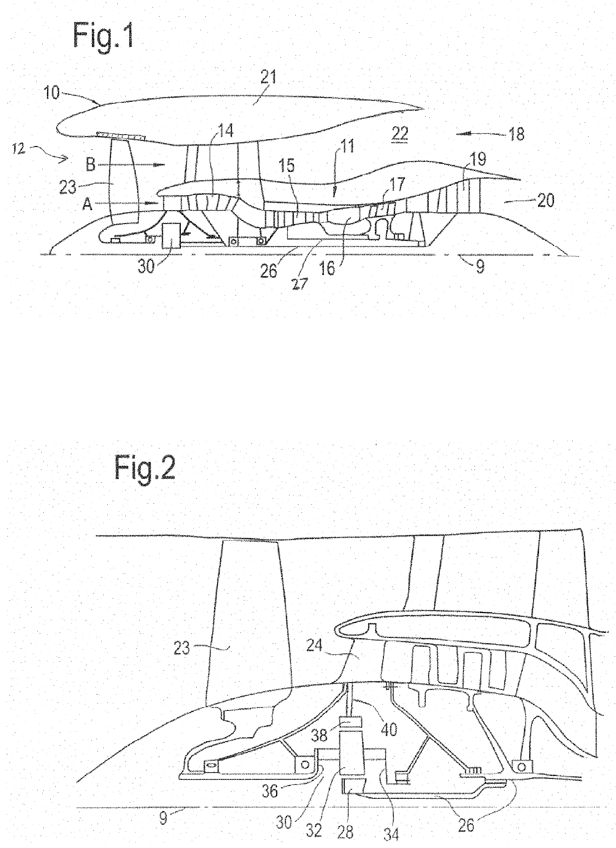
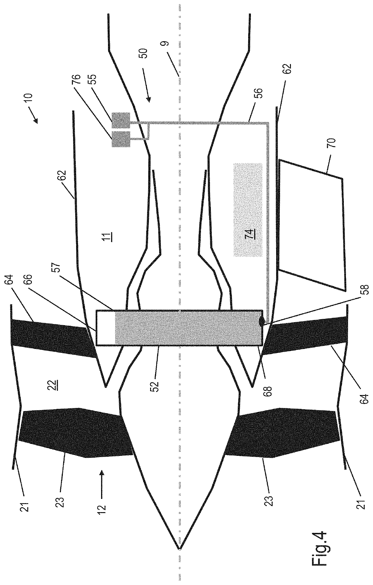
[0039]The present disclosure relates to an oil tank filling system that is useful, for example, in the gas turbine engine of an aircraft.

[0040]Such a gas turbine engine may comprise an engine core comprising a turbine, a combustor, a compressor, and a core shaft connecting the turbine to the compressor. Such a gas turbine engine may comprise a fan (having fan blades) located upstream of the engine core.

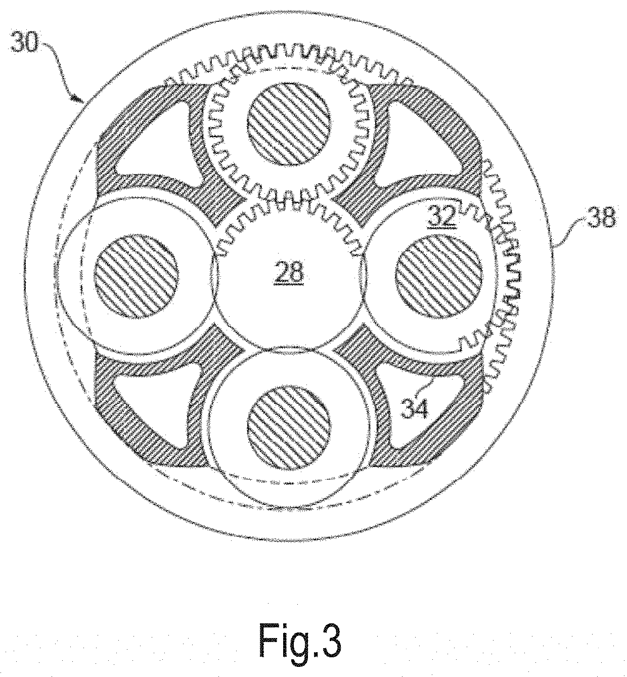
[0041]Arrangements of the present disclosure may be particularly, although not exclusively, beneficial for fans that are driven via a gearbox. Accordingly, the gas turbine engine may comprise a gearbox that receives an input from the core shaft and outputs drive to the fan so as to drive the fan at a lower rotational speed than the core shaft. The input to the gearbox may be directly from the core shaft, or indirectly from the core shaft, for example via a spur shaft and / or gear. The core shaft may rigidly connect the turbine and the compressor, such that the turbine and compressor ro...


PUM


Abstract

An oil tank filling system for filling the oil tank of a gas turbine engine that includes an aft core cowl. The system includes an oil tank that has an oil tank top and an oil tank bottom and is located within a core of the engine, an oil access port located on the aft core cowl; and an oil tank filling pipe that leads from the oil access port to a tank filling port located at or adjacent the oil tank bottom. The system is configured so that oil that is supplied to the oil access port flows to and into the oil tank using gravitational force. A method of filling the oil tank of a gas turbine engine and a gas turbine engine that includes the oil tank filling system are also disclosed.

Description

CROSS-REFERENCE TO RELATED APPLICATIONS[0001]This specification is based upon and claims the benefit of priority from United Kingdom patent application number GB 1807202.5 filed on May 2, 2018, the entire contents of which are incorporated herein by reference.BACKGROUNDField of the Disclosure[0002]The present disclosure relates to an oil tank filling system.[0003]More particularly, the present disclosure provides an oil tank filling system that is useful for a gas turbine engine such as those used to power and propel large passenger aircraft. A method of filling the oil tank of a gas turbine engine and a gas turbine engine that includes the oil tank filling system are also disclosed.Description of the Related Art[0004]Gas turbine engine oil systems are in general full flow re-circulatory systems that must provide for adequate lubrication and cooling of all engine bearings, gears and drive splines under all foreseeable operating conditions.[0005]Each gas turbine engine typically has ...

Claims


Application Information

Patent Timeline
IPC IPC(8): F01D25/20F02K3/06F01M11/00F01M11/04F01M11/12
CPCF02K3/06F01M2011/0033F01M2250/60F01M11/12F01D25/20F01M11/0004F05D2260/98F01M11/0458F05D2220/32B67D7/06B67D7/32F01M11/04F02C7/06F05D2220/36F05D2230/72F16N2210/02F16N7/00Y02T50/60F01D25/18F16N7/02
Inventor EDWARDS, DAVID A.BEWICK, CLARE L.WHITE, SAMUEL W.MALEWICZ, WILLIAM A.RAY, SEBASTIANDIAZ GARCIA, CRISTINA
Owner ROLLS ROYCE PLC
Why Eureka
Try Eureka