Method and system for controlling an ammonia coverage degree profile

a technology of ammonia coverage and ammonia concentration, applied in the direction of engines, mechanical equipment, machines/engines, etc., can solve the problems of increasing the emission of particle mass pm from the engine and increasing the fuel consumption, and achieve the effect of reducing the consumption of reductants and/or fuel and minimizing emissions into the environmen

Active Publication Date: 2019-11-14
SCANIA CV AB
View PDF7 Cites 14 Cited by
  • Summary
  • Abstract
  • Description
  • Claims
  • Application Information

AI Technical Summary

Benefits of technology

[0016]The ammonia / urea dosing control problem comprises several parts of problems. The main objective of the dosing is to achieve a required nitrogen oxides NOx conversion. This conversion could directly be converted into a corresponding ammonia / urea flow. However, depending on operating conditions, a certain surplus is also needed, since the limited residence time in the catalyst does not allow all ammonia NH3 formed from the dosed urea to be consumed by the nitrogen oxides NOx reduction reactions. The surplus increases the ammonia NH3 concentration, and thus also the reaction rate, making it possible to reach the required nitrogen oxides NOx conversion. The urea flow corresponding to the required nitrogen oxides NOx conversion together with the surplus constitutes a static dosing.
[0062]According to an embodiment of the present invention, the control of the sectional ammonia coverage degree profile NH3_profile reduces an ammonia slip NH3_slip from the at least one SCR catalyst to at least one Ammonia Slip Catalyst (ASC) arranged downstream of the at least one SCR catalyst, whereby a generation of nitrous oxide N20 in the at least one ASC is reduced. Hereby, less nitrous oxide N20 is then emitted into the environment from the ASC. Emission of nitrous oxide N20 may in the future be included in emission standards and regulations regarding emissions from combustion engines, wherefore it is advantageous to minimize the nitrous oxide N20 being output from the system, as long as an efficient reduction of nitrogen oxides NOx can still be made efficiently.

Problems solved by technology

Similarly, there is often a negative correlation between a produced particle mass PM and the fuel efficiency, meaning that an increased emission of particle mass PM from the engine is connected with an increased fuel consumption.

Method used


Image

  • Method and system for controlling an ammonia coverage degree profile
  • Method and system for controlling an ammonia coverage degree profile
  • Method and system for controlling an ammonia coverage degree profile

Examples


Embodiment Construction

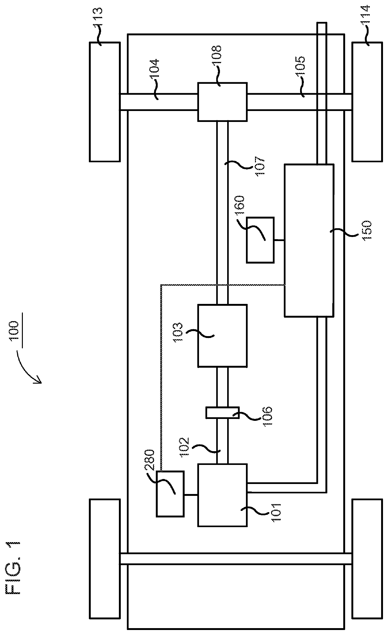
[0092]FIG. 1 schematically shows an example vehicle 100, comprising an exhaust treatment system 150, which may be an exhaust treatment system 150 being controlled according to one embodiment of the present invention. The power-train of the vehicle comprises a combustion engine 101, which in a customary manner, via an output shaft 102 on the combustion engine 101, usually via a flywheel, is connected to a gearbox 103 via a clutch 106.

[0093]The combustion engine 101 is controlled by the vehicle's control system via a control device 280, which may be connected to the exhaust treatment system 150. Likewise, the clutch 106 and the gearbox 103 may be controlled by the vehicle's control system with the help of one or more applicable control devices (not shown). Naturally, the vehicle's driveline may also be of another type, such as a type with a conventional automatic gearbox, of a type with a hybrid driveline, etc.

[0094]An output shaft 107 from the gearbox 103 drives the wheels 113, 114 v...


PUM


Abstract

A method (and a system that executes the method) for control of at least one sectional ammonia coverage degree profile NH3_profile for at least one SCR catalyst included in an exhaust gas treatment system, the method includes determining at least one ammonia sectional coverage degree profile NH3_profile_det for the at least one SCR catalyst based on a flow F, a temperature T and a composition C of the exhaust stream upstream of the at least one SCR catalyst. The method also includes comparing the at least one sectional ammonia coverage NH3_profile_ref with at least one sectional reference profile for an ammonia coverage degree NH3_profile_ref for the at least one SCR catalyst. The method further includes controlling, based on the comparison, at least one of a concentration of nitrogen oxides CNOX in the exhaust stream to be output from the combustion engine and a dosage of a reductant including ammonia NH3 to be injected into the exhaust stream upstream of the at least one SCR catalyst.

Description

TECHNICAL FIELD[0001]The present invention relates to a method for controlling at least one ammonia coverage degree profile for at least one selective catalytic reduction catalyst, according to the preamble of claim 1. The present invention also relates to a system arranged for controlling at least one ammonia coverage degree profile for at least one selective catalytic reduction catalyst, according to the preamble to claim 13. The present invention also relates to a vehicle including the system. The present also relates to a computer program and a computer program product implementing the method according to the invention.BACKGROUND[0002]The following background description is a description of the background to the present invention, and thus need not necessarily be a description of prior art.[0003]In connection with increased government interests concerning pollution and air quality, primarily in urban areas, emission standards and regulations regarding emissions from combustion e...

Claims


Application Information

Patent Timeline
Patent Type & Authority Applications(United States)
IPC IPC(8): F01N3/20F01N9/00
CPCF01N2900/1621F01N2570/18F01N2560/026F01N2570/14F01N2900/0406F01N2900/1622F01N9/00F01N2610/02F01N2560/06F01N3/208F01N2900/1602F01N3/206F01N3/2066F01N2560/02F01N2900/1616Y02T10/12Y02T10/40Y02A50/20
Inventor JOHANSSON, BJÖRNLARSSON, ANDERSWESTERBERG, BJÖRN
Owner SCANIA CV AB
Why Eureka
Try Eureka