Method and system for control of at least one of a dosage device and an engine

a technology of dosage device and engine, which is applied in the direction of electrical control, exhaust treatment electric control, separation process, etc., can solve the problems of back pressure, inability to control the amount to be injected, and formation of residues/precipitates/crystallisations of additives, so as to increase the back pressure in the exhaust treatment system, increase the fuel consumption of the engine, and reduce the effect of general purification performan

Inactive Publication Date: 2020-02-13
SCANIA CV AB
View PDF0 Cites 0 Cited by
  • Summary
  • Abstract
  • Description
  • Claims
  • Application Information

AI Technical Summary

Benefits of technology

[0009]The additive being injected into the exhaust stream is thus very important for the reduction of the nitrogen oxides (NOx) in the exhausts. However, in known solutions, the control of the amount to be injected is not very exact/reliable, which may be problematic. Especially, if too much additive is injected into the exhaust stream, there is a risk that residues/precipitates/crystallisations of additive are formed downstream of the dosage device injecting the additive into the exhaust stream (for example, in an evaporation chamber). Such additive residues/precipitates/cryst

Problems solved by technology

However, in known solutions, the control of the amount to be injected is not very exact/reliable, which may be problematic.
Especially, if too much additive is injected into the exhaust stream, there is a risk that residues/precipitates/crystallisations of additive are formed downstream of the dosage device injecting the additive into the exhaust stream (for example, in an evaporation chamber).
Such additive residues/precipitates/crystallisations (hereafter commonly denoted residues) of additive being formed in the exhaust treatment system potentially increase the back pressure in the exhaust treatment system, and therefore potentially also increase the fuel consumption for the engine.
Also, such additive res

Method used


Image

  • Method and system for control of at least one of a dosage device and an engine
  • Method and system for control of at least one of a dosage device and an engine
  • Method and system for control of at least one of a dosage device and an engine

Examples


Embodiment Construction

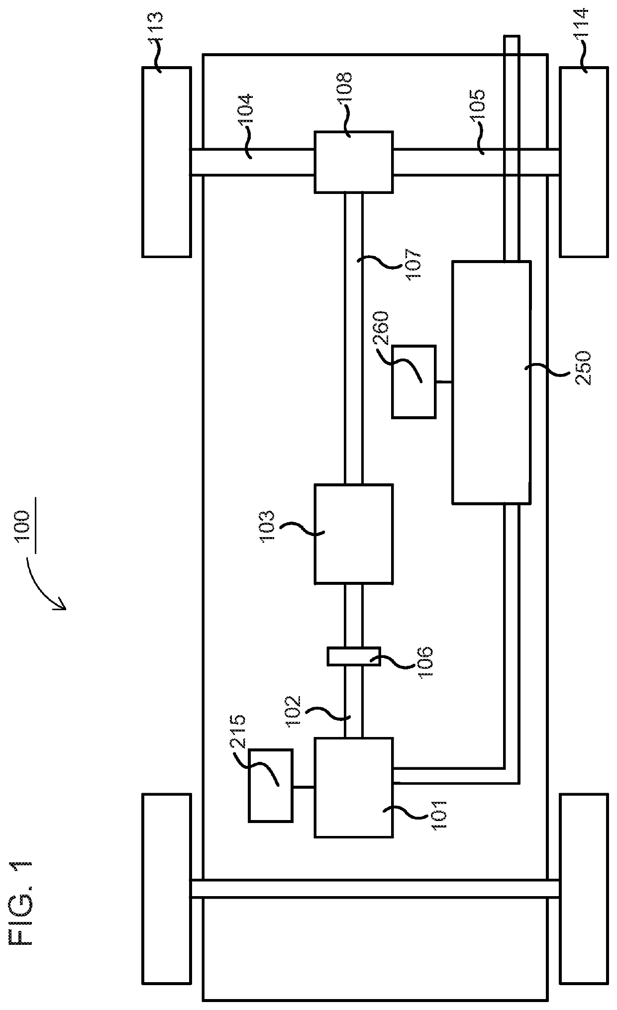
[0101]FIG. 1 schematically shows an example vehicle 100 comprising an exhaust treatment system 250. The powertrain of the vehicle 100 comprises a combustion engine 101, which in a customary manner, via an output shaft 102 on the combustion engine 101, usually via a flywheel, is connected to a gearbox 103 via a clutch 106.

[0102]The combustion engine 101 is controlled by the engine's control system via a control device 215. Likewise, the clutch 106 and the gearbox 103 may be controlled by the vehicle's control system, with the help of one or more applicable control devices (not shown). Naturally, the vehicle's powertrain may also be of another type, such as a type with a conventional automatic gearbox, of a type with a hybrid powertrain, etc. A Hybrid powertrain may include the combustion engine and at least one electrical motor, such that the power / torque provided to the clutch / gearbox may be provided by the combustion engine and / or the electric motor.

[0103]An output shaft 107 from t...


PUM


Abstract

A method and a system for control of a dosage device and/or an engine that produces an exhaust stream (203) treated by an exhaust treatment system (250) that injects at least one additive into the exhaust stream (203) with a dosage device (271) to evaporate in an evaporation chamber (280). The method includes determining a time dependent condition of a position at an internal wall (281) of the evaporation chamber (280), the condition being determined based on the internal temperature related to the position, the internal temperature being determined based on a temperature model for the evaporation chamber (280) and an exhaust temperature for the exhaust stream (203) upstream of the evaporation chamber (208); determining a risk for at least one spatially resolved critical condition related to the position based on the time dependent condition, and controlling the dosage device (271) and/or the engine based on the determined risk.

Description

CROSS-REFERENCE TO RELATED APPLICATIONS[0001]The present application is a 35 U.S.C. § 371 national phase conversion of PCT / SE2018 / 050306, filed Mar. 23, 2018, which claims priority of Swedish Patent Application No. 1750393-9, filed Mar. 31, 2017, the contents of all of which are incorporated herein by reference. The PCT International Application was published in the English language.TECHNICAL FIELD[0002]The present invention relates to a method for controlling at least one of a dosage device and an engine. The present invention also relates to a system arranged for controlling at least one of a dosage device and an engine. The invention also relates to a computer program and a computer-readable medium, which implement the method according to the invention.BACKGROUND[0003]The following background description constitutes a description of the background to the present invention, and thus need not necessarily constitute prior art.[0004]In connection with increased government interests c...

Claims


Application Information

Patent Timeline
IPC IPC(8): F01N3/20F02D41/40F02D41/38F01N9/00F02D41/00
CPCF01N2900/1404F02D2200/04F02D2041/389F02D41/401F01N2900/0412F02D2200/0614F01N3/208F01N2900/1812F01N9/005F01N2900/1811F02D41/0047F01N2900/1411F01N2900/08F02D41/3836F01N2900/0422F01N3/206F01N9/00F01N2560/06F01N2560/07F01N2610/02F01N2900/1821Y02T10/12Y02T10/40B01D53/9418F01N3/2892F01N2900/1602
Inventor BIRGERSSON, HENRIKORRLING, STEFANTEMPELMANN, DAVID
Owner SCANIA CV AB
Why Eureka
Try Eureka