High flow miniature proportional control valve with linear moving magnetic voice coil motor

a proportional control valve, linear moving magnetic voice coil technology, applied in the field of valves, to achieve the effect of minimizing power requirements, high actuation force, and large strok

Active Publication Date: 2019-11-14
PARKER INTANGIBLES LLC
View PDF15 Cites 1 Cited by
  • Summary
  • Abstract
  • Description
  • Claims
  • Application Information

AI Technical Summary

Benefits of technology

[0009]The unique linear moving magnet motor has a minimally narrow magnetic gap which provides high actuation force across a relatively large stroke while minimizing the power required. This is accomplished by creating a flux frame with a narrow magnetic gap in which two narrow rare earth magnets are positioned inside a non-magnetic frame suspended by first and second spring steel beams adjacent to respective magnet elements. The magnet elements are positioned with their poles opposite each other such that when the coils are energized, one magnet is pulled toward the centerline of the flux frame while the other magnet is repelled from the centerline of the flux frame. The two spring steel beams restrain the motion of the non-magnetic frame that houses the magnet elements to an arc with a large enough radius such that the motion is quasi-linear. This makes the actuator silent since there are no contacting parts, which is desirable for users particularly of breathing apparatuses that are used in close proximity to patients.
[0010]The valve operator is constructed such that pressure forces on the inlet or outlet port of the valve are balanced by either the inlet or outlet diaphragm. By substantially balancing the pressure forces the valve can be actuated by a relatively small actuation force. The diaphragms, along with port gasket seals, make the valve operator hermetically sealed from the actuator and the outside environment. This diaphragm balance configuration does not use a small bleed hole to port pressure to the back side of the diaphragm as is commonly done in conventional configurations, which is undesirable because a small bleed hole can be easily plugged by particulates and viscous fluids.
[0011]An aspect of the invention, therefore, is a proportional valve having a narrow magnetic gap to improve actuator performance, and pressure balancing diaphragms that reduce the required actuation force. In exemplary embodiments, the proportional valve includes a valve assembly including a valve body that houses a valve operator. The valve body defines an inlet and an outlet for a fluid flow through the valve body. The valve operator has a longitudinal axis and includes a poppet that is moveable along the longitudinal axis between a closed position and an open position, wherein in the closed position the poppet seals against a valve seat of the valve body to prevent fluid flow between the inlet and the outlet, and in the open position the poppet is moved away from the valve seat to permit fluid flow between the inlet and the outlet. The proportional valve further includes an actuator, wherein the actuator comprises an actuator housing that houses: a first magnet element and a second magnet element; a non-magnetic carrier in which the first magnet element and the second magnet element are mounted; a first wire coil located adjacent to the magnet elements and a second wire coil located adjacent to the magnet elements on an opposite side of the magnet elements relative to the first wire coil; a first spring beam to which the non-magnetic carrier is suspended adjacent to the first magnet element, and a second spring beam to which the non-magnetic carrier is suspended adjacent to the second magnet element; and a flux frame that conducts magnetic field lines through the actuator. When the wire coils are energized, a magnetic field is created which causes the non-magnetic carrier to move against the valve operator to move the valve poppet away from the closed position against the valve seat, thereby opening the valve. The first and second spring beams restrain the movement of the non-magnetic carrier to an arc of sufficient radius that said movement is quasi-linear. The valve operator further includes an inlet diaphragm adjacent to the inlet and an outlet diaphragm adjacent to the outlet that balances pressure forces at the inlet and the outlet.

Problems solved by technology

This diaphragm balance configuration does not use a small bleed hole to port pressure to the back side of the diaphragm as is commonly done in conventional configurations, which is undesirable because a small bleed hole can be easily plugged by particulates and viscous fluids.

Method used


Image

  • High flow miniature proportional control valve with linear moving magnetic voice coil motor
  • High flow miniature proportional control valve with linear moving magnetic voice coil motor

Examples


Embodiment Construction

[0017]Embodiments of the present invention will now be described with reference to the drawings, wherein like reference numerals are used to refer to like elements throughout. It will be understood that the figures are not necessarily to scale.

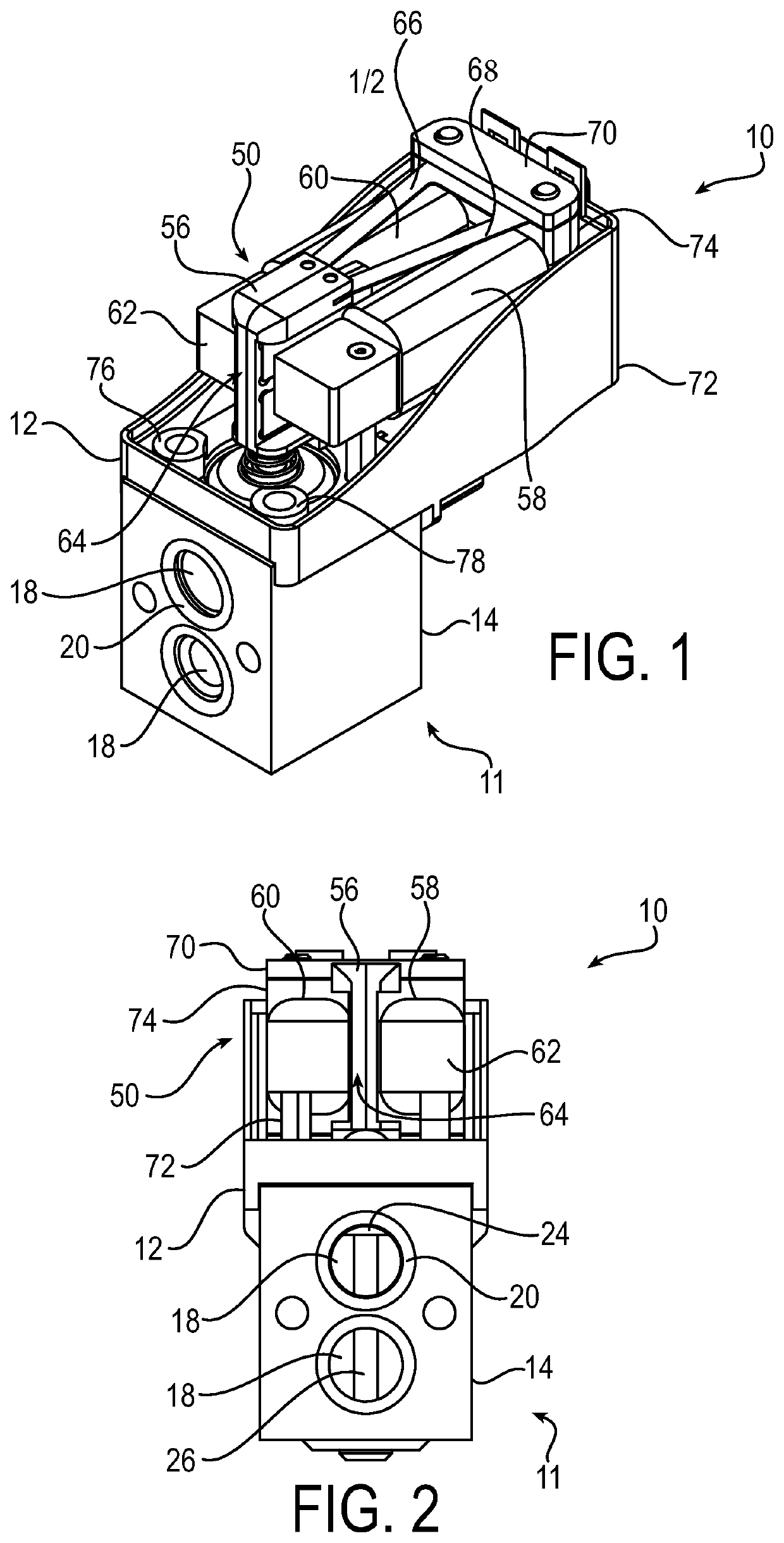
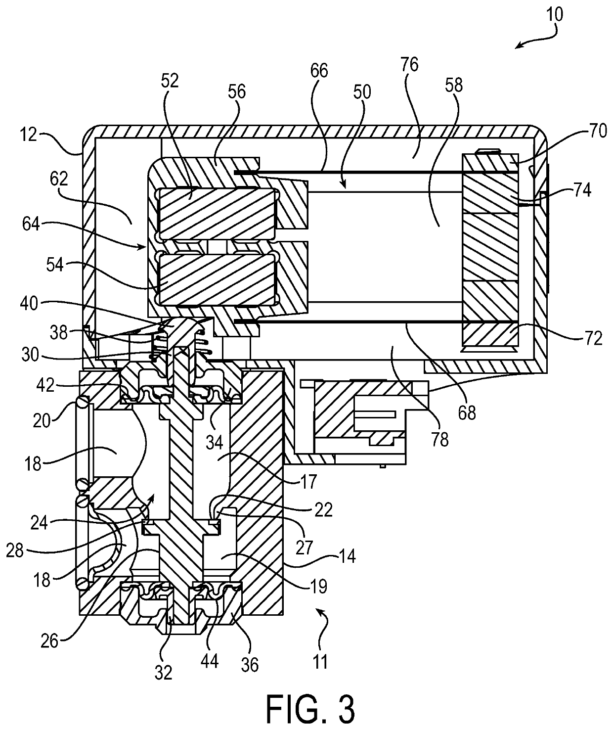
[0018]FIGS. 1-3 depict various views of an exemplary low profile miniature proportional valve 10. The proportional valve 10 generally has a more compact size and uses less materials (less weight) as compared to conventional configurations. The present invention can achieve a valve structure that is less than one third the size and less than one quarter the weight of conventional configurations, for a comparable application. In addition, the configuration of the present invention reduces the number and spatial extent of air gaps, resulting in an enhanced transmission of magnetic flux while maintaining such more compact size and weight as compared to conventional configurations.

[0019]An aspect of the invention, therefore, is a proportional valve...


PUM


Abstract

A proportional valve includes a valve assembly including a valve body that houses a valve operator. The valve body defines an inlet and an outlet for a fluid flow through the valve body. The valve operator has a longitudinal axis and includes a poppet that is moveable along the longitudinal axis between a closed position and an open position. The proportional valve further includes an actuator, wherein the actuator comprises an actuator housing that houses: a first magnet element and a second magnet element; a non-magnetic carrier in which the first magnet element and the second magnet element are mounted; a first wire coil located adjacent to the magnet elements and a second wire coil located adjacent to the magnet elements on an opposite side of the magnet elements relative to the first wire coil; a first spring beam to which the non-magnetic carrier is suspended adjacent to the first magnet element, and a second spring beam to which the non-magnetic carrier is suspended adjacent to the second magnet element; and a flux frame that conducts magnetic field lines through the actuator. When the wire coils are energized, a magnetic field is created which causes the non-magnetic carrier to move against the valve operator to move the valve poppet away from the closed position against the valve seat, thereby opening the valve. The first and second spring beams restrain the movement of the non-magnetic carrier to an arc of sufficient radius that said movement is quasi-linear.

Description

RELATED APPLICATIONS[0001]This application claims the benefit of U.S. Provisional Application No. 62 / 669,697 filed May 10, 2018, the contents of which are incorporated herein by reference.FIELD OF INVENTION[0002]The present invention relates generally to valves, and more particularly to valves for use in high pressure and high flow applications, such as for example in life science and medical applications.BACKGROUND OF THE INVENTION[0003]High pressure and high flow valves are used in a variety of applications. For example, clinical laboratories and hospitals utilize various diagnostic apparatuses to analyze patient medical samples, such as blood, urine, other fluids, and tissues. Such applications further include portable medical devices that aid breathing, such as oxygen concentrators and ventilators. In such apparatuses, high pressure and high flow valves control the flow of gases or other fluids. Because it is desirable for such apparatuses to be as compact as practicable, the si...

Claims


Application Information

Patent Timeline
Patent Type & Authority Applications(United States)
IPC IPC(8): F16K31/04H02K41/035G05D16/20F16K31/06F16K37/00H02K33/18H02K33/02
CPCF16K37/0041F16K31/06H02K41/0354H02K33/18H02K33/02G05D16/2006F16K31/047F16K31/0679F16K31/08F16K31/10F16K41/10G05D16/2022F16K31/0682F16K31/0693F16K31/082
Inventor VERRECCHIA, JOEL J.BURNS, JAMES A.BROWN, EDWIN L.
Owner PARKER INTANGIBLES LLC
Why Eureka
Try Eureka