Valve actuator and diaphragm valve including the same

a valve actuator and diaphragm valve technology, applied in the direction of diaphragm valves, engine diaphragms, operating means/releasing devices of valves, etc., can solve the problems of limited stroke that can be guaranteed, structurally difficult to ensure a large flow rate, and increase in capacity, so as to ensure reliable valve openability and closability, the effect of sufficient air pressur

Active Publication Date: 2019-11-21
KITZ SCT
View PDF2 Cites 0 Cited by
  • Summary
  • Abstract
  • Description
  • Claims
  • Application Information

AI Technical Summary

Benefits of technology

[0033]From the invention according to claim 1, the booster mechanism is configured to be accommodated in any of the air chambers, and therefore the occupying spaces required for both of the air chambers and the booster mechanism are integrated. Thus, while a sufficient valve closing force is ensured, the actuator can be significantly downsized. At the same time, since at least two air chambers are arranged, while an excessive increase in the size of the actuator is avoided, a required air pressure can be sufficiently ensured, and thus a reliable valve-opening force can be guaranteed. Therefore, a significantly-downsized valve actuator also with reliable valve openability and closability can be provided.
[0034]From the invention according to claim 2, the booster mechanism is configured with the paired cam members pivotally attached to one swing shaft and, since the structure of each cam member is simple, a simple structure can be achieve as a whole. Thus, not only productivity, handleability, and maintenability but also durability of the actuator is increased, and the invention is extremely suitable also for downsizing.
[0035]From the invention according to claim 3, with the roller part interposed, sliding between the cam member and the piston can be almost eliminated. Thus, damage on a member and a loss of motive power of the piston, or air contamination due to occurrence of dust due to sliding of both members can be extremely reduced.
[

Problems solved by technology

However, there is a limit to the stroke that can be ensured, and it is structurally difficult to ensure a large flow rate, compared with other valve types such as a bellows valve.
In introducing the clean room, initial cost of equipment, which increases with capacity, and running cost for maintenance and continuous operation are required, which are a large burden as cost of production equipment.
However, as described above, although a further larger closing force is required to achieve a high flow and support high pressure, downsizing of the spring of the actuator is unavoidable with downsizing of the valve, thereby posing a problem of decreasing the pressing force of the spring to decrease the valve closing force.
If the closing force of the valve is impaired, accurate fluid control over process gas is impaired, and a fatal defect in product quality may occur.
Moreover, since the process gas is highly harmful to human bodies, even a small amount of leakages may pose a large problem.
Furthermore, when the installation area is limited by downsizing the valve, applicable springs are limited to those having a predetermined small wire diameter or spring diameter, thereby increasing stress to be added to one spring to pose a problem also in durability of the sprin

Method used


Image

  • Valve actuator and diaphragm valve including the same
  • Valve actuator and diaphragm valve including the same
  • Valve actuator and diaphragm valve including the same

Examples


Embodiment Construction

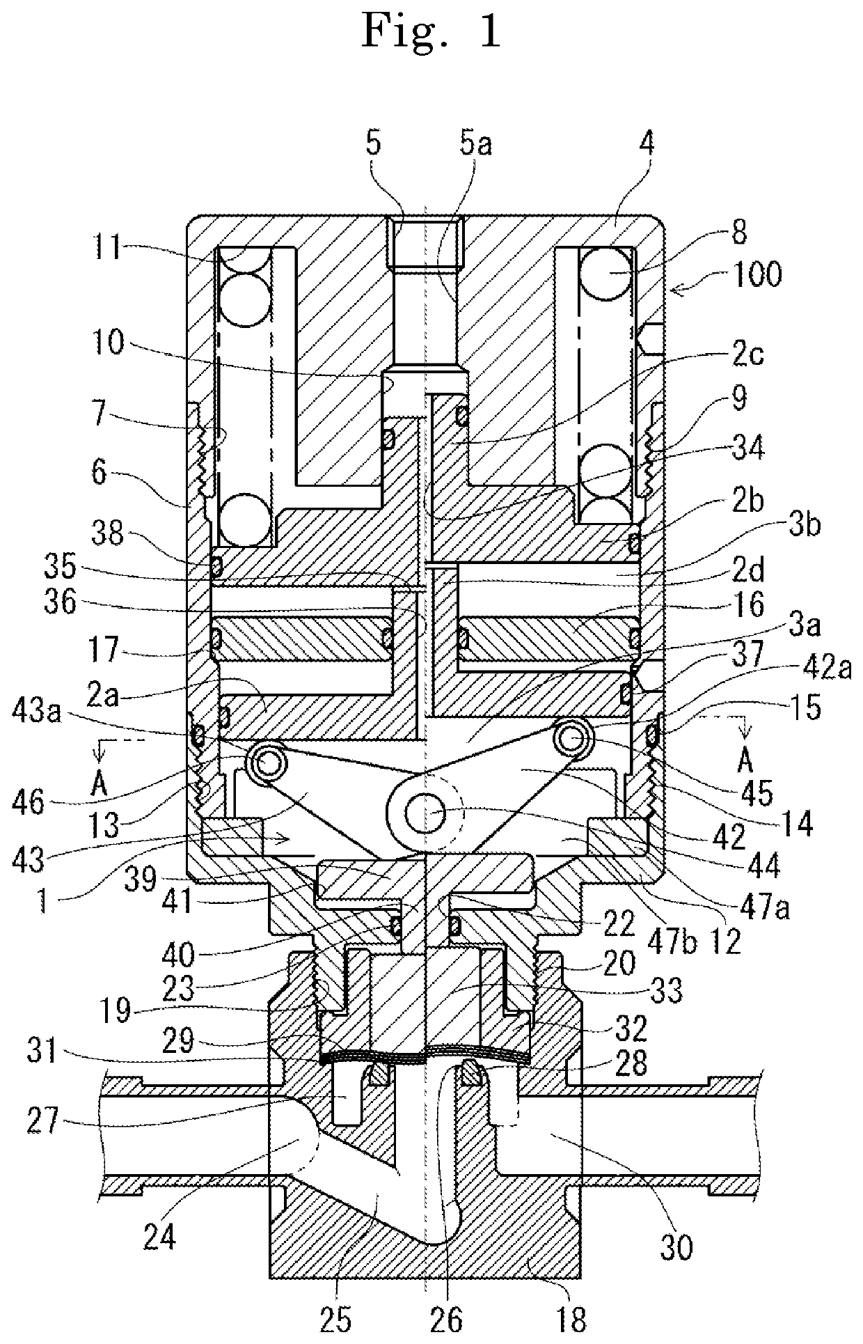
[0043]In the following, a structure of one embodiment of the present invention is described in detail based on the drawings. FIG. 1 is a sectional view of a valve actuator of the present embodiment (present example) and a diaphragm valve of the present example in a state of including the same, in which a left half from a center line in the drawing depicts a full-closed state of the valve of the present example and a right half depicts a full-open state of of the valve of the present example.

[0044]In FIG. 1, the valve actuator of the present example is an air-driven actuator having arranged therein a piston 2 pressed by a repulsive member 8 (spring 8) provided in an actuator main body 100 and at least two air chambers 3 (3a, 3b) for moving the piston 2 by air pressure and having a booster mechanism 1 for causing a force amplified in a valve-close direction to be exhibited accommodated in any of the air chambers 3.

[0045]A cover 4 assumes an outer appearance with a substantially cylind...


PUM


Abstract

Provided is a valve actuator in a simple structure and easily downsizable, having reliable valve openability and closability even under high pressure, and also capable of exerting high durability even with a high frequency of valve opening and closing, and a diaphragm valve including this valve actuator. In the valve actuator, a repulsive member provided in an actuator main body, a piston pressed by this repulsive member, and at least two air chambers for moving the piston by an air pressure are arranged and a booster mechanism for exerting a force amplified in a valve-closing direction is accommodated in any of the air chambers.

Description

TECHNICAL FIELD[0001]The present invention relates to a valve actuator and a diaphragm valve including the same and, in particular, to a valve actuator extremely suitably configured for downsizing of the entire valve structure while exerting high valve closability also for a high-pressure fluid and a diaphragm valve including the valve actuator.BACKGROUND ART[0002]In general, as a control valve for a gas supply system in semiconductor manufacturing process or the like, a so-called direct-touch-type diaphragm valve is mainly used. The direct diaphragm valve has its advantages in which the seat is directly closed also with a metal diaphragm for use as a material for sealing outside, a very simple flow path without having extra components in a gas contact part can be configured, and this is thus thought to be an optimum structure for cleaning a fluid, without a part where metals slide each other inside the gas contact part. However, there is a limit to the stroke that can be ensured, a...

Claims


Application Information

Patent Timeline
IPC IPC(8): F16K7/16F16K31/524F16K31/163
CPCF16K7/16F16K31/163F16K31/52491F15B15/02F15B15/14F16K7/17Y02T10/12F16K31/524
Inventor KOU, CHOKUTO
Owner KITZ SCT
Why Eureka
Try Eureka