
Railway wagon compartment suitable for small limitation bound

A railway freight car, small limit technology, applied in the direction of railway car body, railway car body parts, freight cars, etc., can solve the problems of increasing manufacturing complexity and product cost, poor strain effect of vehicle limit, increasing locomotive traction energy consumption, etc. Achieve the effects of improving stability and safety, simple structure, and low vehicle weight

Active Publication Date: 2013-06-19
CHONGQING CHANGZHENG HEAVY IND
View PDF6 Cites 15 Cited by
  • Summary
  • Abstract
  • Description
  • Claims
  • Application Information

AI Technical Summary

Problems solved by technology

[0003] (1) The strain effect on the vehicle boundary is not good, especially when the width of the connection between the lower part of the vehicle side wall and the floor needs to meet the requirements of mechanization (such as: electric shovel) for unloading bulk goods, the smaller boundary width at this height (such as: south Africa’s railway limits) have poor adaptability, which affects the safety of vehicle operation;
[0004] (2) Since the corner columns are usually made of pressed angle steel or cold-formed rectangular hollow section steel, or welded by channel steel and corner column plates, there are many manufacturing processes in the production process, which increases the manufacturing complexity and product cost;
[0005] (3) The weight of the carriage is relatively large, which reduces the transportation efficiency and increases the traction energy consumption of the locomotive

Method used


Image

  • Railway wagon compartment suitable for small limitation bound
  • Railway wagon compartment suitable for small limitation bound
  • Railway wagon compartment suitable for small limitation bound

Examples


Embodiment Construction

[0024] The present invention will be further described below in conjunction with drawings and embodiments.

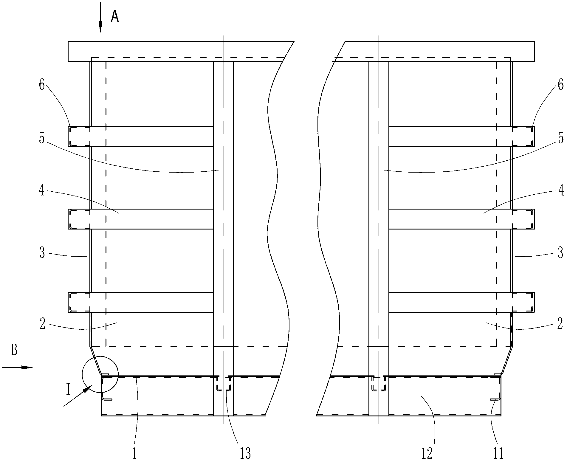
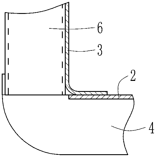
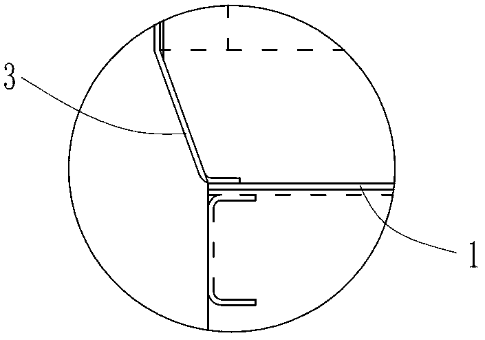
[0025] combine figure 1 —— Figure 4 The shown railway freight car compartment suitable for small limits consists of a floor 1, two side wall panels 2, two end wall panels 3, a plurality of side transverse strips 4, a plurality of side columns 5, a plurality of end transverse strips 6, End beams 11, side beams 12, transverse beams 13 and the like.

[0026] The side wall panels 2 are located on the left and right sides of the floor 1, and the end wall panels 3 are located at the front and rear ends of the floor 1. figure 1 The essence is the view of the observer standing in the left (right) direction of the carriage, Figure 4 It is essentially a view of the observer standing in the front (rear) position of the carriage. Both sides of the floor 1 are bent upwards to form an upper flange, and the lower part of the side wall panel 2 is bent inward to form an inclinat...


PUM


Abstract

The invention discloses a railway wagon compartment suitable for a small limitation bound. The railway wagon compartment suitable for the small limitation bound comprises a floor (1), lateral wall plates (2) located on two sides of the floor (1) and end wall plates (3) located at two ends of the floor (1). The lower portion of each lateral wall plate (2) is bent inwards to form a dip angle, connected with the floor (1) in a lap joint mode and fixed with the floor (1) through welding. The lower portion of each end wall plate (3) is bent inwards to form a dip angle, connected with the floor (1) in a lap joint mode and fixed with the floor (1) through welding. Two sides of each end wall plate (3) are connected with corresponding ends of each lateral wall plate (2) in a lap joint mode and fixed with the corresponding ends of each lateral wall plate (2) through welding. The dip angles bent inwards are arranged on the lower portions of the lateral wall plates and the lower portions of the end wall plates, so that corner posts and corner post plates in a traditional structure are cancelled. Furthermore, through the arrangement of lateral vertical columns, lateral platbands and end platbands, entire intensity of the compartment is improved. On the premise that the requirement of a railway of a small limitation bound is met, the loading capacity of the compartment is increased to the maximum limit. The railway wagon compartment suitable for the small limitation bound is easy to manufacture, small in self weight, safe and efficient in transportation.

Description

technical field [0001] The invention belongs to the field of railway transportation equipment, and in particular relates to a carriage structure of a railway freight car. Background technique [0002] The structure of the traditional railway freight car is as follows: Figure 5 , Figure 6 and Figure 7 As shown, it is composed of floor 1, side wall panel 2, end wall panel 3, side column 5, end beam 11, side beam 12, transverse beam 13, corner post 7, corner post plate 8 and other components. The end beams 11, side beams 12, and transverse beams 13 are welded into a rectangular frame structure. The floor 1 is welded above the frame structure. The end beams 11 are located at the front and rear ends of the floor 1. The beams 13 are distributed along the length direction of the floor 1 , and the side beams 12 and the transverse beams 13 are perpendicular to each other. The outer surface of the side beam 12 is welded and fixed to the side wall panel 2, and a corner post 7 is ...

Claims


Application Information

Patent Timeline
Patent Type & Authority Applications(China)
IPC IPC(8): B61D17/00B61D3/00
Inventor 付玲
Owner CHONGQING CHANGZHENG HEAVY IND
Learn More