Coupling flange assembly for connecting steel pipes
a technology of coupling flanges and steel pipes, which is applied in the direction of machines/engines, mechanical equipment, and final product manufacture, etc., can solve the problems of large hoop stress of pipe walls, and limited thickness of flange plates b>1/b>, so as to reduce the force on welding seams, reduce the effect of bending moment of stiffening plates on connecting, and reduce the effect of hoop stress
- Summary
- Abstract
- Description
- Claims
- Application Information
AI Technical Summary
Benefits of technology
Problems solved by technology
Method used
Image
Examples
embodiment 1
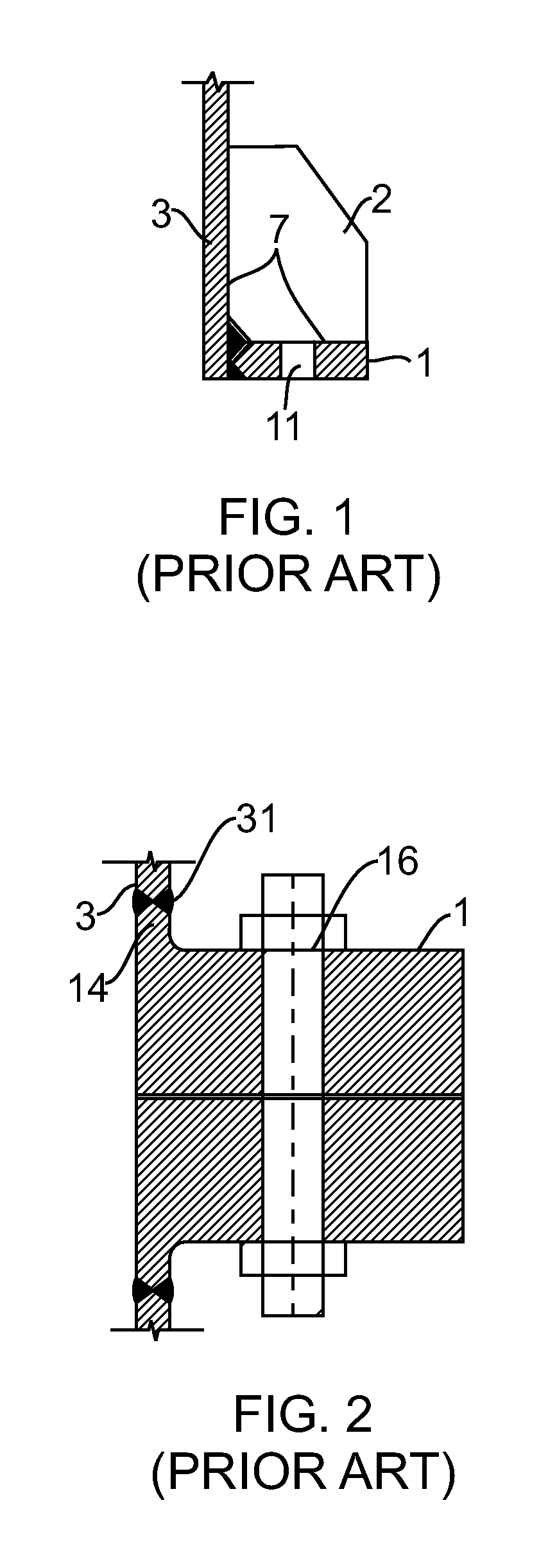
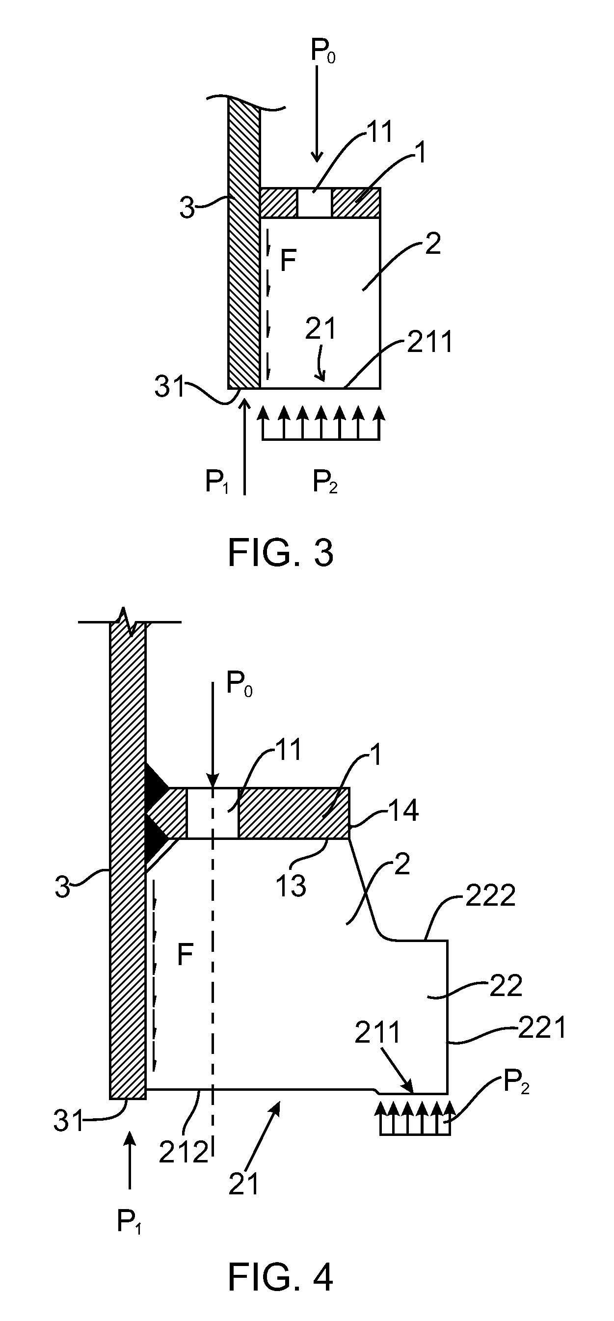
[0053]As shown in FIG. 3, this invention provides a flange assembly comprising Flange Plate 1 and Stiffening Plates 2. In this embodiment, said Flange Plate 1 and Stiffening Plates 2 are located on the inner side of Steel Pipe 3, forming an internal flange assembly. The central axis of the upper and lower Steel Pipe 3 lies on the right of the figure. Several Bolt Holes 11 are set up on Flange Plate 1. Preferably, said Stiffening Plates 2 are evenly distributed along the wall of Steel Pipe 3. Said Bolt Holes 11 are located on the splitting line between the center lines of two neighboring Stiffening Plates 2. As a matter of fact, if there are just a few stiffening plates and each of them is thick enough, Bolt Holes 11 can also go through the main bodies of Stiffening Plates 2. This is optional. Said Bolt Holes 11 just have to connect the two abutting flange assemblies through fastening pieces such as bolts. Stiffening Plates 2 are located on the front side of Flange Plate 1 along the ...
embodiment 2
[0060]See FIG. 3-6. This embodiment basically has the same principles, structure, and effects as Embodiment 1, which will not be repeated here. The difference is: in this embodiment, said Flange Plate 1 and Stiffening Plates 2 are located on the outer side of Steel Pipe 3. Said flange assembly is embodied as an outer flange assembly. This embodiment basically has the same structure as Embodiment 1. Only the inner and outer flanges are different. The central axis of Steel Pipe 3 lies on the right of the figure. Please refer to Embodiment 1 for the details of the structure. They will not be repeated here.
embodiment 3
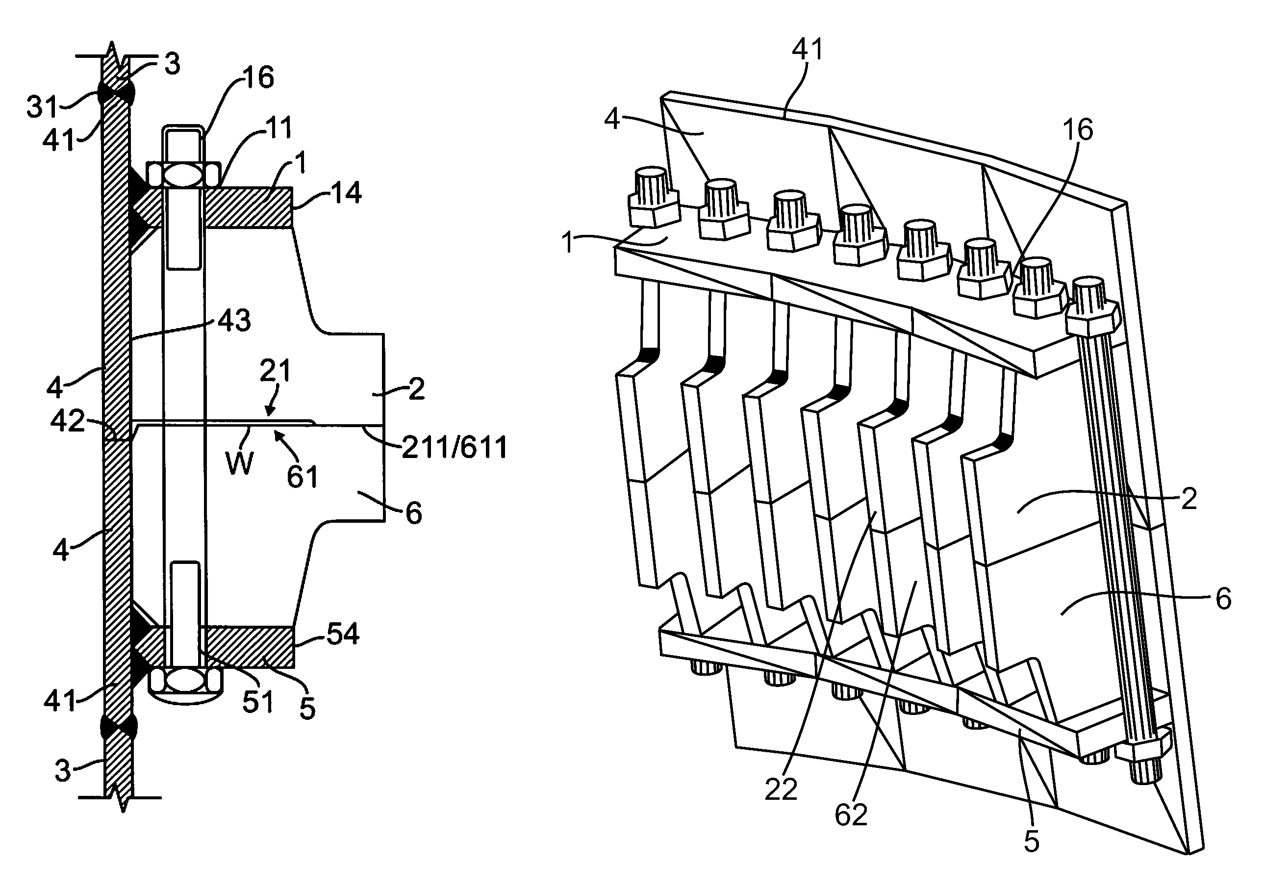
[0061]See FIG. 5. This embodiment basically has the same principles, structures, and effects as Embodiment 1, which will not be repeated here. The difference is that the coupling flange of this embodiment directly comprises an upper assembly and a lower flange assembly fitted together.
[0062]This coupling flange comprises an upper flange assembly and a lower flange assembly. The upper flange assembly comprises an Upper Flange Plate 1 and several Upper Stiffening Plates 2. The lower flange assembly comprises a Lower Flange Plate 5 and several Lower Stiffening Plates 6. In this embodiment, said Upper Flange Plate 1, Lower Flange Plate 5, Upper Stiffening Plates 2, and Lower Stiffening Plates 6 are located on the inner side of Upper and Lower Steel Pipes 3. This coupling flange is an inner coupling flange. The center axis of Upper and Lower Steel Pipes 3 is on the left of the figure.
[0063]Bolt Holes 11 and Bolt Holes 51 are set up respective Upper Flange Plate 1 and Lower Flange Plate 5...
PUM
 Abstract
Description
Claims
Application Information
 - R&D
- Intellectual Property
- Life Sciences
- Materials
- Tech Scout
- Unparalleled Data Quality
- Higher Quality Content
- 60% Fewer Hallucinations
Browse by: Latest US Patents, China's latest patents, Technical Efficacy Thesaurus, Application Domain, Technology Topic, Popular Technical Reports.
© 2025 PatSnap. All rights reserved.Legal|Privacy policy|Modern Slavery Act Transparency Statement|Sitemap|About US| Contact US: help@patsnap.com


