Rotating electric machine

a technology of rotating electric machines and rotating shafts, which is applied in the direction of dynamo-electric machines, electrical apparatus, magnetic circuits, etc., can solve the problems of reducing the capacity of magnetic flux generation, reducing the amount of output, and reducing the optimal dimensions of magnetic circuits, so as to suppress claw-shaped magnetic pole portions, and reduce the capability of short circuit portions

Active Publication Date: 2019-05-23
DENSO CORP
View PDF0 Cites 10 Cited by
  • Summary
  • Abstract
  • Description
  • Claims
  • Application Information

AI Technical Summary

Benefits of technology

[0017]According to this configuration, when the field magnetic flux is excited by the field core upon energization of the field winding, the magnetic flux flowing through the boss portion wound with the field winding becomes saturated, so that the magnetic force ψm of the permanent magnet can flow out to the stator. Therefore, the magnetic force ψm of the permanent magnet allows a magnetic three to be increased by an amount greater than or equal to a decrease in the capability of a short circuit portion, provided between conventional claw-shaped magnetic pole portions, due magnetic flux leakage. Consequently, the field characteristics and the maximum magnetic flux can be set high, leading to high output.
[0018]The magnetic flux short circuit member is disposed on the outer side or the inner side of claw-shaped magnetic pole portions, or in a space excluding the area of permanent magnet, located between claw-shaped magnetic pole portions having circumferentially arranged to have different polarities. If the magnetic flux short circuit member is disposed on the outer side of the claw-shaped magnetic pole portions, the resistance of the claw-shaped magnetic pole portions to the centrifugal force increases in radial directions. This suppresses the claw-shaped magnetic pole portions from expanding radially outward by the centrifugal force. Therefore, the air gap between the stator and the rotor can have the same size as for conventional Lundell-type rotors with no magnets, which constitute a majority of rotors distributed. Consequently, sufficient reliability in strength is secured while the expansion of the air gap is suppressed. In addition, the smaller air gap lowers the field current flowing through the field winding, thus reducing the amount of heat generated by the field winding as compared with conventional Lundell-type rotors with magnets. Thus, thermal reliability can be achieved with the capability of an existing air-cooling mechanism.

Problems solved by technology

However, widening the air gap increases the magnetoresistance and thus reduces the capability of magnetic flux generation due to the field current of the rotor.
This approach, however, does not provide optimum dimensions for magnetic circuits, thus reducing the amount of output.
However, this technique involves a factor in reducing the amount of output compared to the configuration of PTL 1 as described in PTL 2, and thus has not been into practical use.
Accordingly, the field current needs to be large, which increases copper losses, leading to increased heat generation.
This approach, however, reduces a space for the field winding, thus increasing heat generation due to an increase in the DC resistance value, and reducing ease of mounting due to an increase in the axial dimensions.

Method used


Image

  • Rotating electric machine
  • Rotating electric machine
  • Rotating electric machine

Examples


first embodiment

[0049]The rotating electric machine according to the first embodiment will be described with reference to FIGS. 1 to 11, 19, and 20. The rotating electric machine according to the first embodiment is a vehicle alternator mounted on a vehicle and used as a generator.

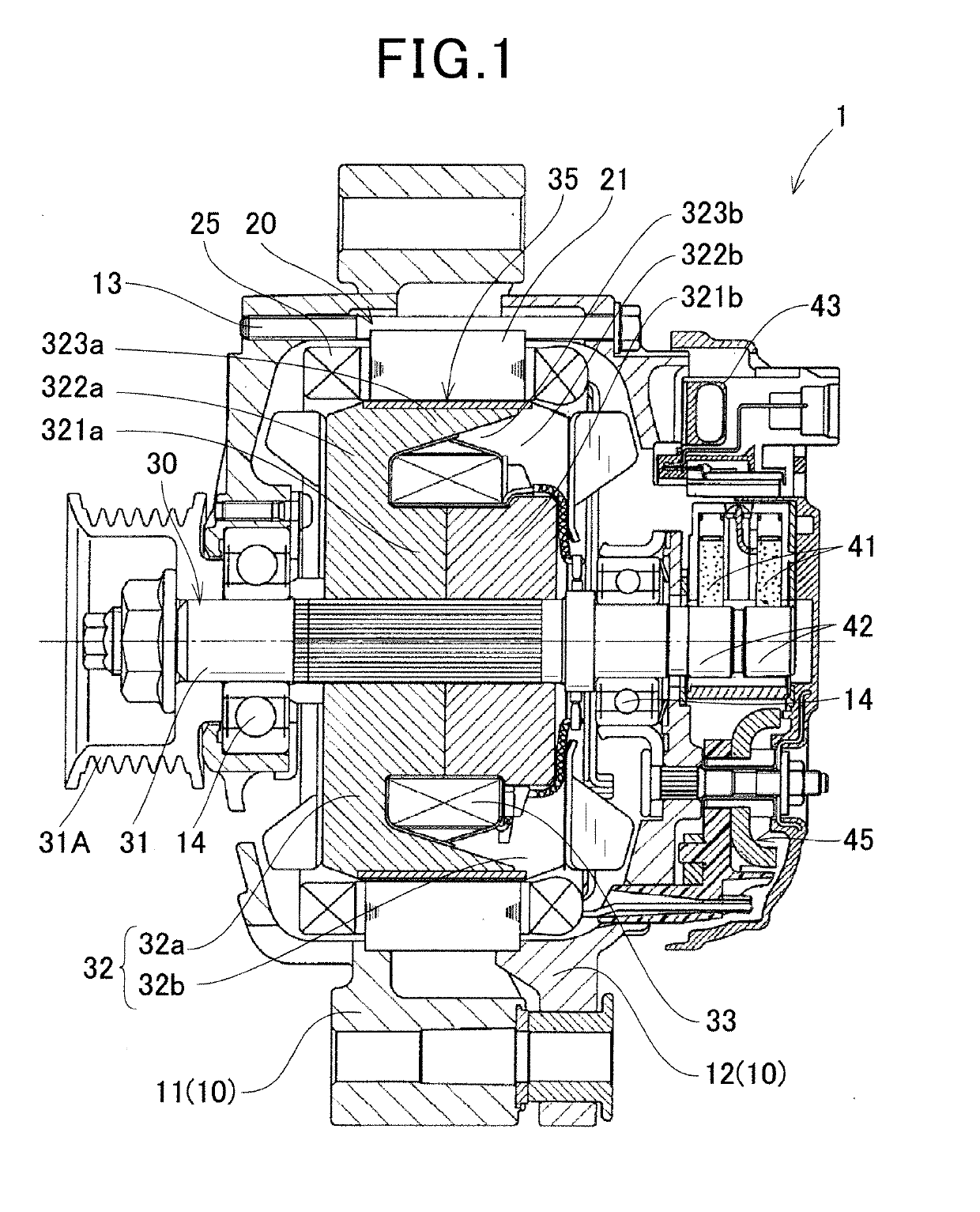
[0050]As shown in FIG. 1, a vehicle alternator 1 of the first embodiment includes a housing 10, a stator 20, a rotor 30, a field winding power supply device, a rectifier 45, and the like. The housing 10 includes a front housing 11 having a cylindrical shape with a closed-bottom and a rear housing 12, each having an open end. The front housing 11 and the rear housing 12 are fastened by bolts 13, with the open portions joined to each other.

[0051]The stator 20 includes an annular stator core 21 having a plurality of slots 22 and a plurality of teeth 23 shown in FIGS. 19 and 20 arranged in the circumferential direction, and armature windings 25 formed of three-phase windings wound in the slots 22 of the stator core 21. The pl...

first modification

[First Modification]

[0075]As shown in FIG. 10, the first modification differs from the first embodiment in the structure of the magnetic flux short circuit member 36. The magnetic flux short circuit member 36 of the first modification is also formed of a soft magnetic material in a hollow cylindrical shape with a constant wall thickness, but differs from the magnetic flux short circuit member 35 of the first embodiment in that a plurality of window portions 36b are formed in areas radially facing the permanent magnet 34 disposed between the claw-shaped magnetic pole portions 323 adjacent in the circumferential direction of the field core 32. The window portions 36b extend in directions inclined from the axial direction along the circumferential side surface of the claw-shaped magnetic pole portions 323, and are circumferentially arranged in alternately reversed directions.

[0076]The magnetic flux short circuit member 36 is fitted and secured to the outer surface of the field core 32 ...

second modification

[Second Modification]

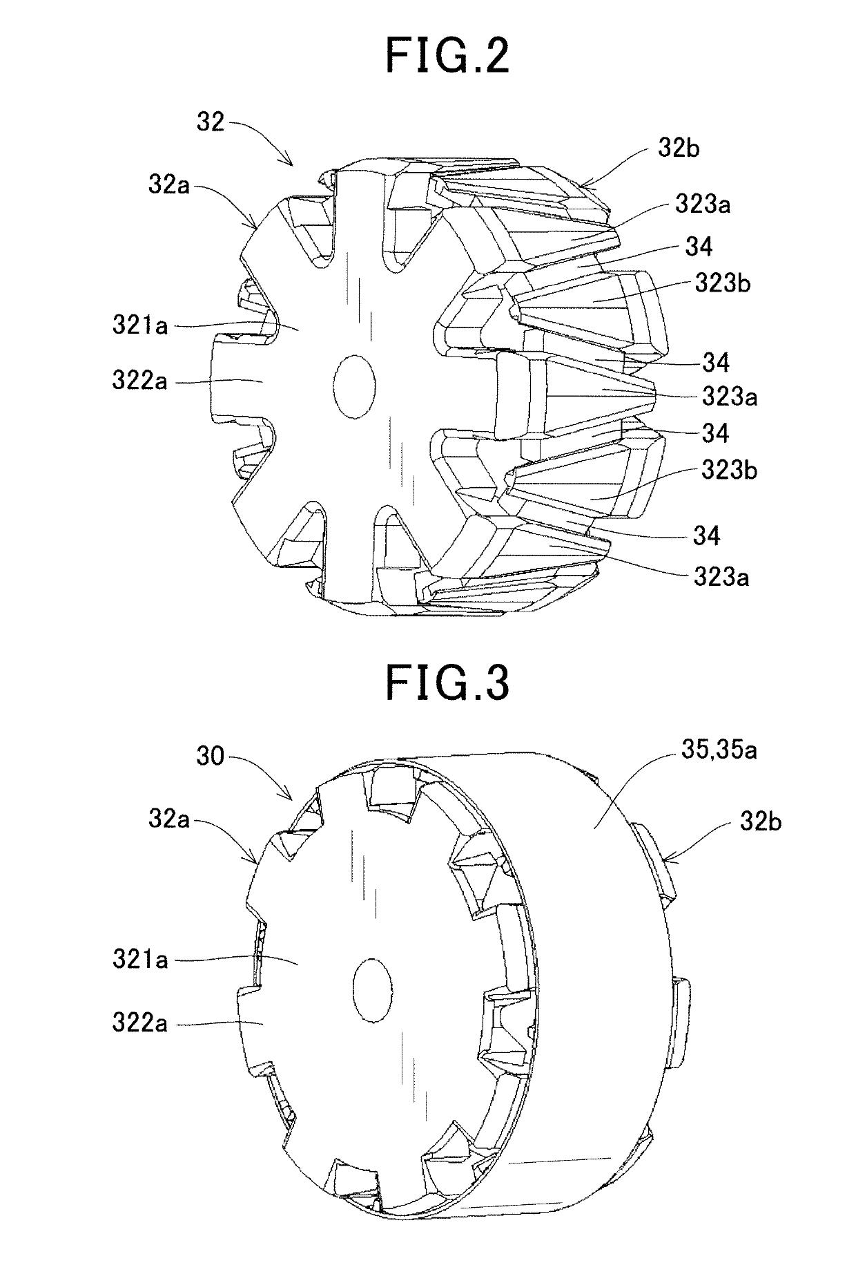
[0077]As shown in FIG. 11, the magnetic flux short circuit members 37 of a second modification correspond to the two short circuit portions 36a at both axial ends of the magnetic flux short circuit member 36 of the first modification. That is, the magnetic flux short circuit members 37 are formed of two ring-shaped members arranged at both axial ends of the field core 32. As with the short circuit portions 36a of the first modification, one of the magnetic flux short circuit members 37 connects the root portions of the first claw-shaped magnetic pole portions 323a and the tip portions of the second claw-shaped magnetic pole portions 323b, while the other magnetic flux short circuit member 37 connects the tip portions of the first claw-shaped magnetic pole portions 323a and the root portions of the second claw-shaped magnetic pole portions 323b.

[0078]The magnetic flux short circuit member 37 of the second modification, with the axially central portion eliminated...


PUM


Abstract

A rotor of a rotating electric machine includes a field core having a cylindrical boss portion, and a plurality of claw-shaped magnetic pole portions that are arranged on the outer side of the boss portion and form poles of alternately different polarities in the circumferential direction, a field winding that is wound around the outer periphery of the boss portion and generates a magnetomotive force by energization, a permanent magnet disposed between the circumferentially adjacent claw-shaped magnetic pole portions so as to have its easy axis of magnetization oriented in the circumferential direction and have its polarity coincide with the polarity of the claw-shaped magnetic pole portions which alternately appears by excitation, and a magnetic flux short circuit member having a short circuit portion that magnetically connects the claw-shaped magnetic pole portions circumferentially arranged to have different polarities.

Description

CROSS-REFERENCE TO RELATED APPLICATION[0001]This application claims the benefits of priority to Patent Application No, 2016-112278, filed Jun. 3, 2016, and Patent Application No. 2017-89433, filed Apr. 28, 2017, the entire contents of which are incorporated herein by reference.TECHNICAL FIELD[0002]The present disclosure relates to a rotating electric machine for use as an electric motor or a generator mounted on, for example, an automobile or a truck.BACKGROUND ART[0003]Conventional rotating electric machines are known that include a Lundell-type rotor having a field winding for generating a magnetomotive force by energization and a plurality of claw-shaped pole pieces in which NS magnetic poles are alternately excited along a circumferential direction of rotation by the magnetomotive three of the field winding. PTL 1 and 2 each discloses a vehicle alternator in which permanent magnets are interposed between claw-shaped pole pieces adjacent in the circumferential direction to increa...

Claims


Application Information

Patent Timeline
Patent Type & Authority Applications(United States)
IPC IPC(8): H02K21/04
CPCH02K21/044H02K2213/03H02K1/276
Inventor TAKAHASHI, YUKIHISADA, TOMOKAZU
Owner DENSO CORP
Why Eureka
Try Eureka