Eureka AIR delivers breakthrough ideas for toughest innovation challenges, trusted by R&D personnel around the world.

Fourier domain dynamic correction method for complex optical fringes in laser spectrometers

Active Publication Date: 2019-11-21
IBM CORP +1
View PDF0 Cites 0 Cited by
  • Summary
  • Abstract
  • Description
  • Claims
  • Application Information

AI Technical Summary

Benefits of technology

The present invention provides a computer-implemented method and computer program product for dynamic correction of optical fringes in a laser spectrometer. This involves Fourier transforming the background spectrum to obtain baseline fringes, partitioning the baseline fringes using bandpass filtering to obtain partitioned baseline fringes, and reconstructing the partitioned baseline fringes as separate spectra using an inverse Fourier transform. A fitting model is then constructed to approximate the background spectrum by assigning parameters to each partitioned baseline fringe component to allow for drift and amplitude adjustments. This model is then applied to a newly acquired spectrum to provide an interpretation with reduced influence of spectral contamination on concentration retrieval. The technical effect of this invention is to improve the accuracy and reliability of laser spectrometer measurements, particularly in cases where optical fringes are present.

Problems solved by technology

Optical interference effects produce fringe noise which is present in most spectroscopic systems that utilize coherent laser sources.
However, since the fringes can change in time due to external effects (e.g., changes in temperature, pressure, and so forth), the fringes can be misinterpreted by spectral fitting routines as the useful spectral signature of the target analyte, which causes unwanted drift in spectroscopic sensing systems.

Method used


Image

  • Fourier domain dynamic correction method for complex optical fringes in laser spectrometers
  • Fourier domain dynamic correction method for complex optical fringes in laser spectrometers
  • Fourier domain dynamic correction method for complex optical fringes in laser spectrometers

Examples


Embodiment Construction

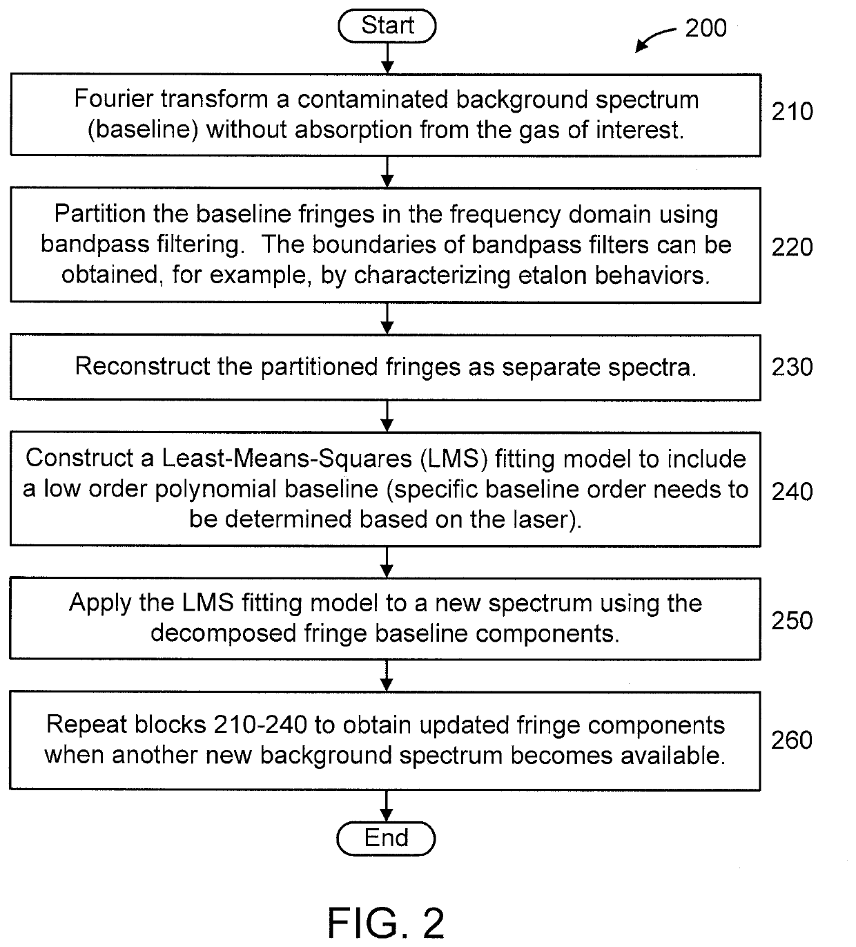
[0018]The present invention is directed to a Fourier domain dynamic correction (removal) method for complex optical fringes in laser spectrometers.

[0019]In an embodiment, the present invention provides a novel method that improves concentration retrieval from a direct absorption spectrum contaminated by complex fringe noise.

[0020]In an embodiment, the present invention is designed to improve the stability of laser-based direct absorption spectroscopy systems affected by fringe noise. The novel features of the present invention are particularly useful for low-cost spectroscopy systems where it may not be possible to address fringes through meticulous system engineering that is often required to reduce optical fringing. As an example, the present invention is suitable for the integrated silicon photonic waveguide sensors that suffer from extensive fringe noise. Of course, the present invention can be applied to other types of sensors and systems, while maintaining the spirit of the pr...


PUM


Abstract

A method is provided for Fourier domain dynamic correction of optical fringes in a laser spectrometer. The method includes Fourier transforming a background spectrum contaminated with the optical fringes to obtain baseline fringes in a frequency domain. The method includes partitioning the baseline fringes in the frequency domain using bandpass filtering to obtain partitioned baseline fringes. The method includes reconstructing the partitioned baseline fringes as separate spectra using an inverse Fourier transform. The method includes constructing a fitting model to approximate the background spectrum by assigning a first and a second free parameter to each of partitioned baseline fringe components to respectively allow for drift and amplitude adjustments during a fitting of the fitting model. The method includes applying the fitting model to a newly acquired spectrum to provide an interpretation of the newly acquired spectrum having a reduced influence of spectral contamination on concentration retrieval.

Description

STATEMENT REGARDING FEDERALLY SPONSORED RESEARCH OR DEVELOPMENT[0001]This invention was made with Government support under Contract Number DE-AR0000540 awarded by the U.S. Dept. of Energy. The Government has certain rights in this invention.BACKGROUNDTechnical Field[0002]The present invention generally relates to optical devices, and more particularly to a Fourier domain dynamic correction method for complex optical fringes in laser spectrometers.Description of the Related Art[0003]Optical interference effects produce fringe noise which is present in most spectroscopic systems that utilize coherent laser sources. Over the past decades, there have been many approaches to suppress this fringe noise. However, since the fringes can change in time due to external effects (e.g., changes in temperature, pressure, and so forth), the fringes can be misinterpreted by spectral fitting routines as the useful spectral signature of the target analyte, which causes unwanted drift in spectroscopic ...

Claims


Application Information

Patent Timeline
IPC IPC(8): G01J3/453G01J3/433G01N21/3504
CPCG01J2003/423G01J3/4338G01N21/3504G01J3/453G01J3/42G01J3/28
Inventor TENG, CHEYENNEWYSOCKI, GERARDZHANG, ERIC J.GREEN, WILLIAM M.
Owner IBM CORP
Why Eureka
Eureka Blog
Learn More