
Radome for vehicles

a technology for radome and vehicles, applied in the direction of antennas, antenna adaptation in movable bodies, antenna lighting/illumination, etc., can solve the problems of unsightly internal parts of the vehicle, reducing the appearance of the radar window, and affecting the appearance of the front grille, etc., to achieve the effect of improving the decoration function

Active Publication Date: 2019-11-21
ZANINI AUTO GRUP
View PDF14 Cites 13 Cited by
  • Summary
  • Abstract
  • Description
  • Claims
  • Application Information

AI Technical Summary

Benefits of technology

The present invention provides a radome for vehicles that includes a rear transparent cover with a maximized coupling of a light source placed inside. This allows the light rays to propagate freely and unobstructed inside the rear transparent cover before being projected towards the vehicle forward direction. The radome maintains its metallic aspect in any lighting condition, improving its decorative function while preserving radar functionality. The technical effect is improved vehicle decoration while maintaining radar functionality.

Problems solved by technology

However, the radar window diminished the appearance of the front grill due to the interruption of the pattern of the grill structural elements.
Further, unsightly internal portions of the vehicle, like the radar transmitter-receiver, could be seen through the radar window.
However, in this radome, its metallic aspect can be lost in the absence of ambient light.

Method used


Image

  • Radome for vehicles
  • Radome for vehicles
  • Radome for vehicles

Examples


first embodiment

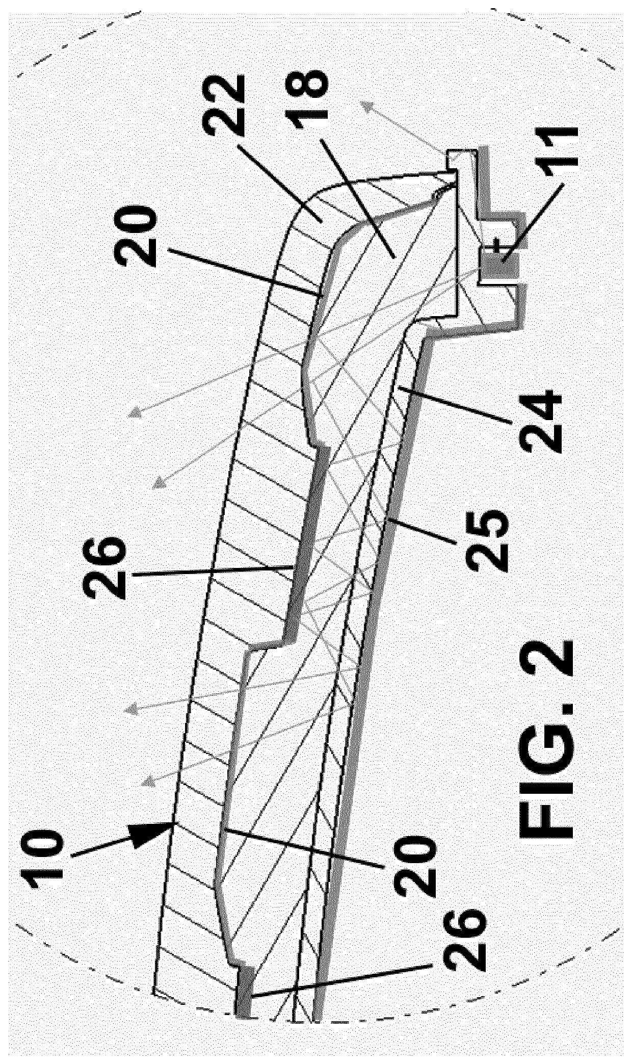
[0026]FIG. 2 is a cross section of the radome 10 according to a

[0027]In this first embodiment, the radome 10 comprises a frontal transparent cover 22, that can be made from an injected transparent material with excellent optical properties.

[0028]This frontal transparent cover 22 can include one or more pads 26 printed on it, or by any other suitable decoration method such as over-injection or hot stamping, and it can also include indentations and recesses on the internal surface, as shown in FIG. 2.

[0029]The radome 10 according to the invention also comprises an intermediate substrate 18, which is preferably injected with a light diffusion material which scatters light, and a decoration layer 20 made from a metalloid or a metalloid alloy, that is preferably coated by PVD Magnetron Sputtering, using a low electrical conductivity element with metallic aspect.

[0030]The thickness of the decoration layer 20 is such that light is partially reflected and partially transmitted, but the meta...

second embodiment

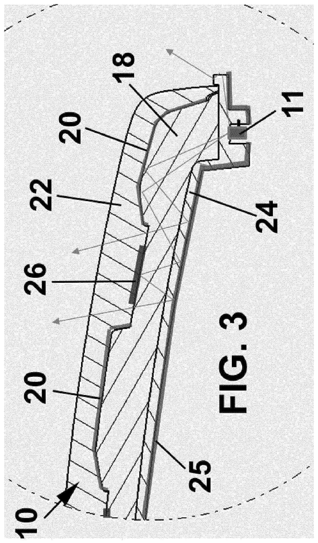
[0039]FIG. 3 shows the radome 11 according to the present invention.

[0040]In this embodiment, the same numeral references are used for identifying the same or equivalent elements for clarity reasons. Furthermore, only the differences between this second embodiment with the first embodiment are described for simplicity reasons.

[0041]The main difference from said first embodiment is that the decoration layer 20 is opaque, and reflects the light back to the reflective coating 25 of the rear transparent cover 24.

[0042]For this reason, the decoration on the front transparent cover 22 (e.g. said at least one pad 26) and on the substrate 18 (said decoration layer 20) are not aligned, so that there is a gap between them, for instance following any identifiable brand logo shapes.

[0043]Therefore, illumination is visible through the existing gap between the decoration layer 20 and the pad(s) 26.


PUM


Abstract

The radome (10) for vehicles comprises a substrate (18) formed of a radio transmissive resin, the substrate (18) having a proximal face and a distal face and a decoration layer (20) applied to the proximal face, the decoration layer (20) comprising a metalloid or a metalloid alloy deposited on the surface of the proximal face, a transparent frontal cover (22) overlying the decoration layer (20), and a light source (11) that illuminates the substrate (18), so that the light from the light source (11) crosses the transparent frontal cover (22). It permits to maintain its metallic aspect in any lighting condition, so that the decorative function is be improved by adding illumination in appropriate conditions while preserving the radar functionality.

Description

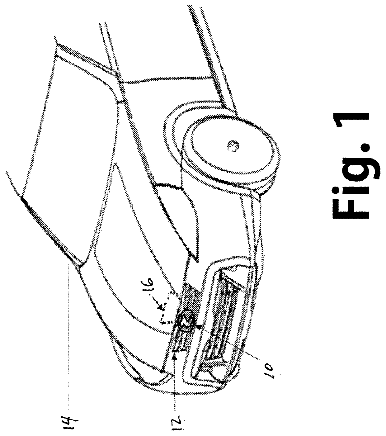
[0001]The present invention refers to a radome for protecting a radar device while presenting a decorative metallic image, especially for radar devices disposed behind the front grill of an automobile.BACKGROUND OF THE INVENTION[0002]In general, radio transmitter-receiver devices, such as a millimeter-wave radar, have been employed as sensors for vehicular collision avoidance and adaptive cruise control systems.[0003]In a radar system or the like that measures obstacles in front of an automobile and the distance between automobiles, the antenna was preferably positioned in the center at the front of the vehicle to obtain maximum performance. Although the radar antenna could be installed near the front grill of automobile, it was preferable to conceal the antenna from view due to its non-aesthetic appearance and to shield the antenna from external environmental factors such as weather and airborne contaminants.[0004]In order protect the antenna and avoid radio interference and signal...

Claims


Application Information

Patent Timeline
IPC IPC(8): H01Q1/42H01Q1/32
CPCH01Q1/3233H01Q1/42H01Q1/3283H01Q1/06H01Q1/422B60Q1/0011
Inventor MAYER PUJADAS, AUGUSTOSANAHUJA CLOT, JOSÉ
Owner ZANINI AUTO GRUP
Learn More