
System and method for determining the position of a vehicle for automated driving on a site

a technology of automated driving and system and method, which is applied in the direction of process and machine control, using reradiation, instruments, etc., can solve the problems of large installation and calibration effort, inaccuracy of gps sensors, and cost of such systems, and achieves affordable and precise end-of-line automation

Active Publication Date: 2019-11-28
ROBERT BOSCH GMBH
View PDF0 Cites 2 Cited by
  • Summary
  • Abstract
  • Description
  • Claims
  • Application Information

AI Technical Summary

Benefits of technology

The present invention provides a system and method that allows for affordable and precise end-of-line automation. This helps to improve the efficiency and accuracy of production processes.

Problems solved by technology

The problem with the system described are the inaccuracies of the GPS sensors in some areas, the extensive installation and calibration effort, as well as the costs of such systems.
In addition, a time-consuming calibration of each vehicle after its final assembly may be omitted.
This may prevent ambiguities in the evaluation of the reflected beams, as a result of which a less efficient control unit is usable.
This may also lower the costs of the auxiliary device.

Method used


Image

  • System and method for determining the position of a vehicle for automated driving on a site
  • System and method for determining the position of a vehicle for automated driving on a site
  • System and method for determining the position of a vehicle for automated driving on a site

Examples


Embodiment Construction

[0031]The same structural elements in the figures each have the same reference numerals.

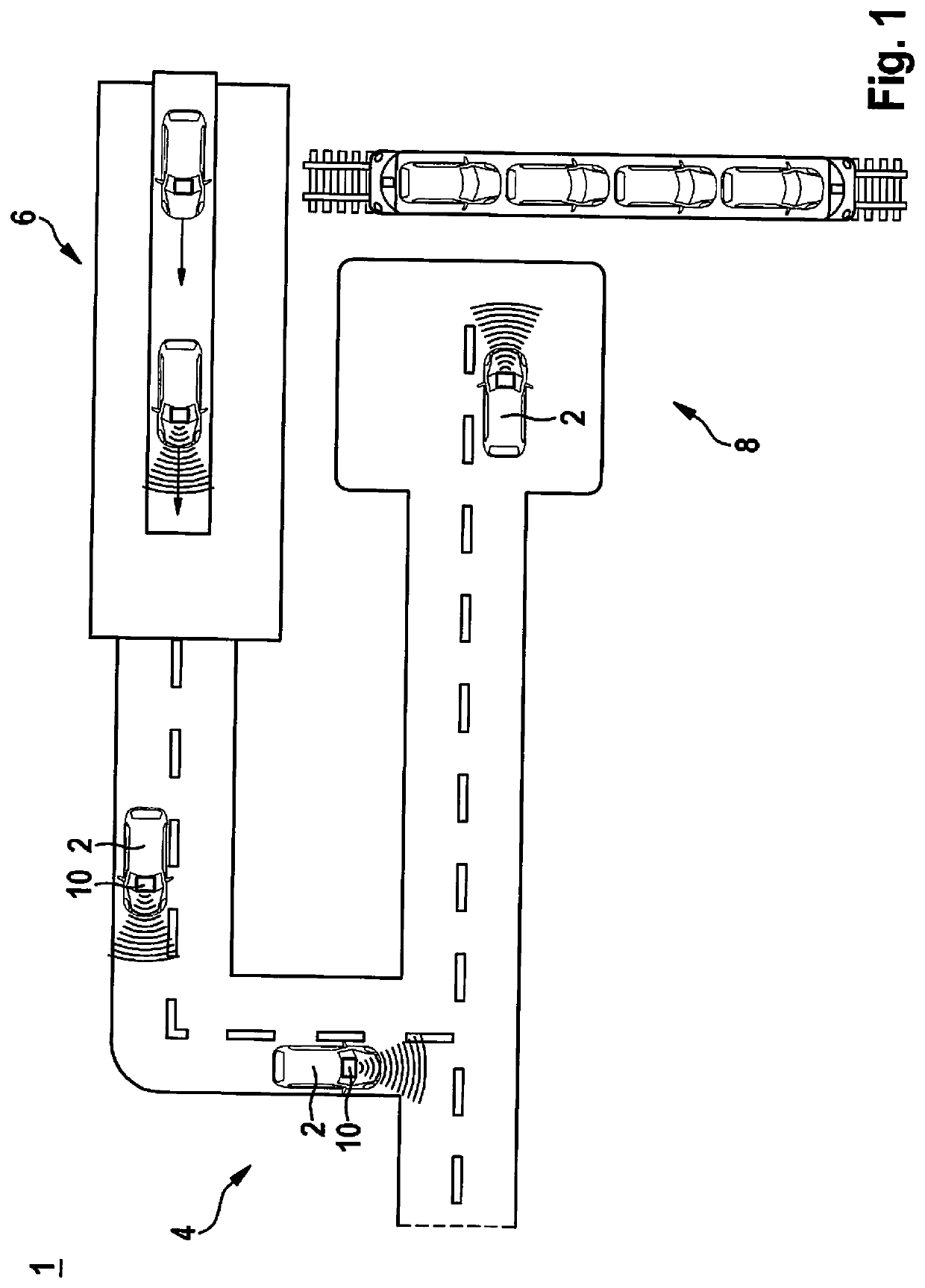
[0032]FIG. 1 shows a system 1 for determining the position of a vehicle 2 on a site 4 and for calculating a trajectory according to one specific embodiment of the present invention.

[0033]According to the exemplary embodiment, site 4 is designed in the form of factory grounds. A so-called end-of-line is positioned in a factory work floor 6, at which vehicles 2 undergo final assembly and are subsequently driven in an automated manner to a transfer point 8, where they are then loaded.

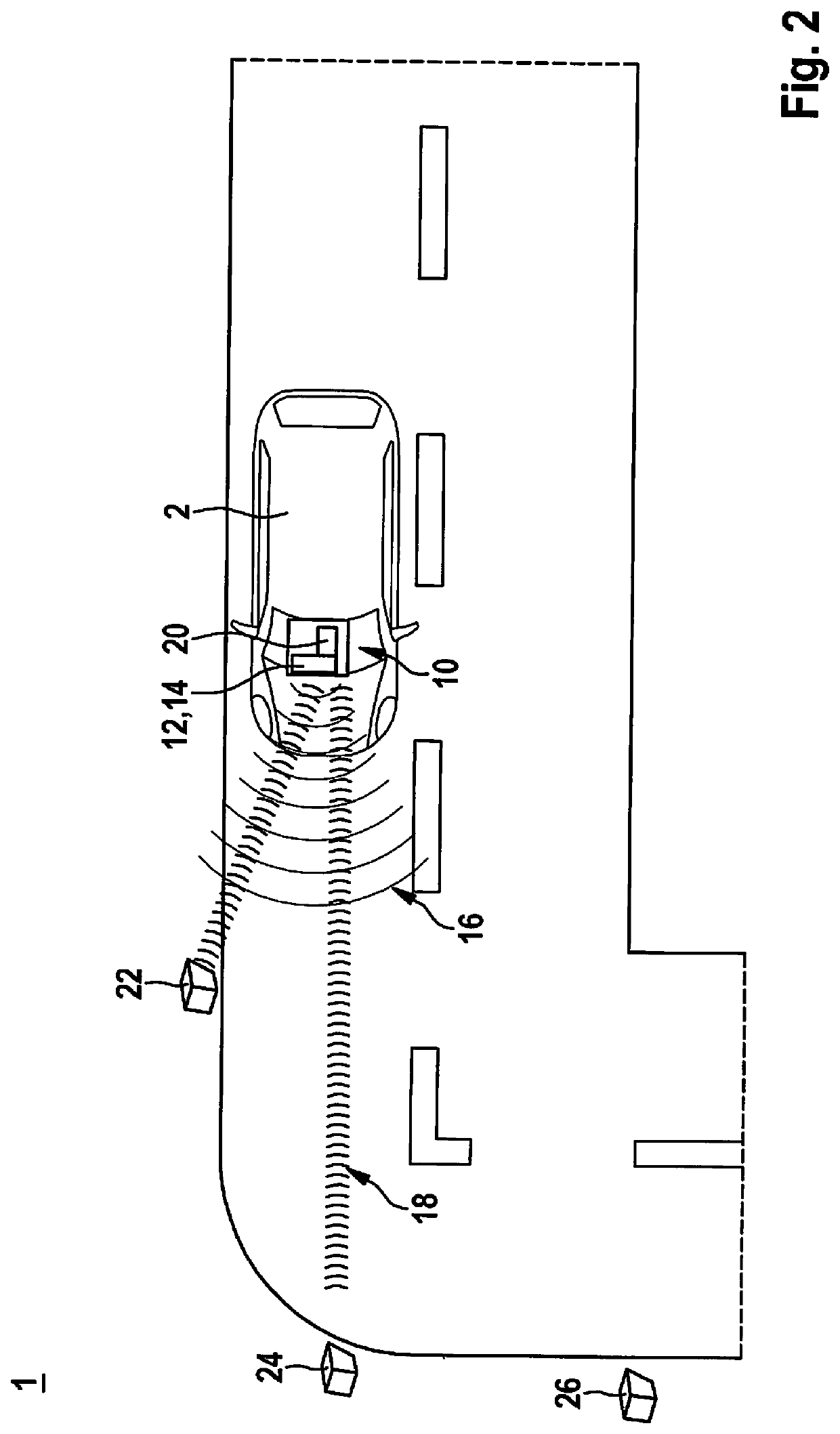
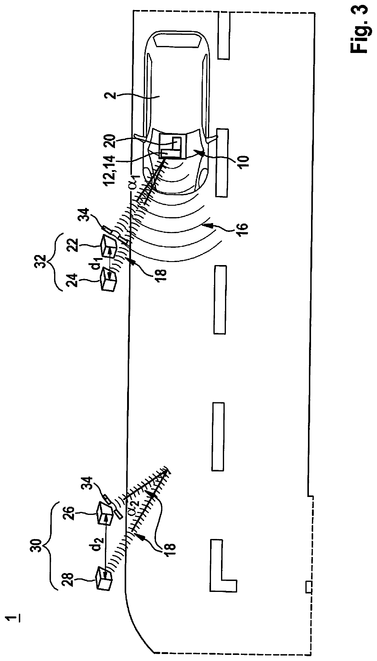
[0034]Vehicles 2 are equipped with auxiliary devices 10 at end-of-line 6. For this purpose, auxiliary devices 10 are mounted, for example, on a vehicle roof and electronically coupled via connection cables to respective vehicle 2. Auxiliary device 10 is depicted in greater detail in FIG. 2.

[0035]Each vehicle 2 includes an auxiliary device 10, with which vehicle 2 is steered in an automated manner within site 4 to transf...


PUM


Abstract

A system is described for determining the position of a vehicle on a site and for calculating a trajectory, including at least one vehicle, at least one auxiliary device and at least one reflector element, the at least one reflector element being mounted in the surroundings of the vehicle along a designated route section and the auxiliary device being suitable for transmitting and receiving electromagnetic beams. A method is also described.

Description

FIELD OF THE INVENTION[0001]The present invention relates to a system for determining the position of a vehicle on a site and for calculating a trajectory, including at least one vehicle, at least one auxiliary device and at least one reflector element, as well as a method for navigating a vehicle along a trajectory and for determining the position of the vehicle on a site.BACKGROUND INFORMATION[0002]In many present vehicles, radar systems are installed, in particular for ascertaining distances and for detecting surroundings of a vehicle. With the emission of electromagnetic beams, the so-called primary beams or primary signals, and the reflection of the electromagnetic beams on objects, a reflected portion of the beams or secondary signal is received and evaluated based on various criteria in order to determine pieces of information such as, for example, distance or dimension of the object.[0003]In order to equip a vehicle for automated driving, the technology required for such pur...

Claims


Application Information

Patent Timeline
Patent Type & Authority Applications(United States)
IPC IPC(8): G05D1/02
CPCG05D1/0236G05D1/024G05D1/0242G05D1/0257G05D1/0259G05D1/0225G05D1/0214G05D1/0221G05D1/0278G05D1/0276G01S7/40G01S13/931B62D15/00G01S17/06G01S13/06G01S2013/9329G05D1/0212G05D1/0244
Inventor TIETZE, NILSWEISSENMAYER, SIMON
Owner ROBERT BOSCH GMBH
Learn More