Mesh Subdivision Method for Complicated Pores in Rock Core

A grid subdivision and grid technology, applied in special data processing applications, instruments, electrical digital data processing, etc., can solve problems such as time-consuming, labor-intensive, and time-consuming

Active Publication Date: 2017-03-15
CHINA PETROLEUM & CHEM CORP +1
View PDF3 Cites 0 Cited by
  • Summary
  • Abstract
  • Description
  • Claims
  • Application Information

AI Technical Summary

Problems solved by technology

However, this method is difficult to generate a high-quality grid with an ideal grid surface ratio. The generation process takes a lot of time, and the node division on the geometric boundary must be done manually. Therefore, it is difficult to achieve a real The grid is automatically generated, which is time-consuming and labor-intensive in practical applications

Method used


Image

  • Mesh Subdivision Method for Complicated Pores in Rock Core
  • Mesh Subdivision Method for Complicated Pores in Rock Core
  • Mesh Subdivision Method for Complicated Pores in Rock Core

Examples


Embodiment Construction

[0032] In order to make the above and other objects, features and advantages of the present invention more comprehensible, preferred embodiments are listed below and described in detail in conjunction with the accompanying drawings.

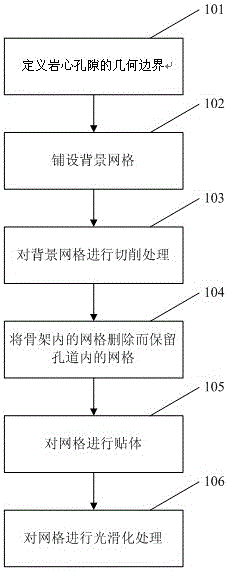
[0033] like figure 1 as shown, figure 1 It is a flow chart of the meshing method for the complex pores of the rock core of the present invention. In step 101, the geometric boundaries of core pores are defined. During the grid generation process, the boundary of the core pores needs to be specified by the user, and the specified format can be CAD format (such as: obj format or STL format, etc.). Due to the extremely complex geometry of the tunnel, non-defined surface points are automatically completed by spline interpolation. The process goes to step 102.

[0034] In step 102, a background grid is laid out for the target calculation area. A right-angle grid is laid on the CAD geometry of the core calculation area as the background grid. The ...


PUM


Abstract

The invention provides a mesh generation method for core complex pores. The mesh generation method for the core complex pores comprises a first step of computing a regional laying background mesh aiming at a core target; a second step of cutting the background mesh by use of a mesh cutting algorithm; a third step of deleting the mesh in a skeleton and retaining the mesh in the pores; a fourth step of performing body fitting on the mesh generated by the cutting algorithm; and a fifth step of smoothing the mesh generated by the cutting algorithm. According to the mesh generation method for core complex pores, an accurate and automatic technology capable of cutting any pore structure of mesh is created, so that the complex geometry in the interior of the core is descripted accurately, and a foundation is laid for core microcosmic flow numerical simulation.

Description

technical field [0001] The invention relates to the related technical field of oil reservoir numerical simulation and oil and gas field development to enhance oil recovery, in particular to a grid division method for complex pores of rock cores. Background technique [0002] The oilfields in the eastern oil regions of my country have generally entered the period of ultra-high water cut, and the distribution of remaining oil tends to be complex and scattered, making it increasingly difficult to enhance oil recovery. Classical reservoir numerical methods are based on the macroscopic seepage theory system, and cannot understand the microscopic structure and properties of oil-water distribution characteristics. Using microscopic numerical simulation technology to study the relative permeability curve, capillary pressure curve and remaining oil distribution law of reservoir cores under different microscopic pore structure parameters is of great significance to the improvement of ...

Claims


Application Information

Patent Timeline
Patent Type & Authority Patents(China)
IPC IPC(8): G06F17/50
Inventor 戴涛张世明孟薇苏军伟孙红霞易红霞李宗阳曹伟东段敏陈苏赵莹莹李珊珊张波
Owner CHINA PETROLEUM & CHEM CORP
Why Eureka
Try Eureka