Roof-mounted Solar Modules Integration Device, Solar Power Vehicle and Encapsulation Method for Modules

Inactive Publication Date: 2019-11-28
DONG HAN NEW ENERGY VEHICLE TECH CO LTD
View PDF0 Cites 2 Cited by
  • Summary
  • Abstract
  • Description
  • Claims
  • Application Information

AI Technical Summary

Benefits of technology

The present invention provides a roof-mounted solar module integration device, a solar power vehicle, and an encapsulation method for modules. The invention solves the problem of inaccuracy in electrical wiring control by forming trenches and through-holes in the substrate to arrange bypass diodes, anti-reversion diodes, and conductive bands. This increases the amount of incident light of the solar module, simplifies the process, and improves the accuracy of electrical arrangement.

Problems solved by technology

1. The integration system with a solar module adds to the weight of the vehicle roof, which is detrimental to the vehicle's lightweight design;
2. The integration and construction operations for the electrical system of the solar module are faced with great difficulties;
3. As for diodes, conductive bands and electrical wire harnesses that are associated with the integration of the solar module, the accuracy of their arrangement positions is hard to control, and their construction is difficult;
4. As limited by the light transmittance of the encapsulation materials themselves, the encapsulation efficiency of the solar module is reduced;
5. As there are gaps between these encapsulation materials and the cell, the cell encapsulation effects would be affected by such external factors as water vapor, air and thermal expansion, such that sealability demands on encapsulation processes are extremely high.

Method used


Image

  • Roof-mounted Solar Modules Integration Device, Solar Power Vehicle and Encapsulation Method for Modules
  • Roof-mounted Solar Modules Integration Device, Solar Power Vehicle and Encapsulation Method for Modules
  • Roof-mounted Solar Modules Integration Device, Solar Power Vehicle and Encapsulation Method for Modules

Examples


Embodiment Construction

[0039]The embodiments of the present invention will now be described below in detail, and their examples are illustrated in the accompanying drawings, in which identical or similar reference numerals denote identical or similar elements or elements having identical or similar functions throughout the views. The embodiments described below with reference to the accompanying drawings are exemplary, which are merely used for explaining the present invention, and not intended to be interpreted as limitations on the present invention.

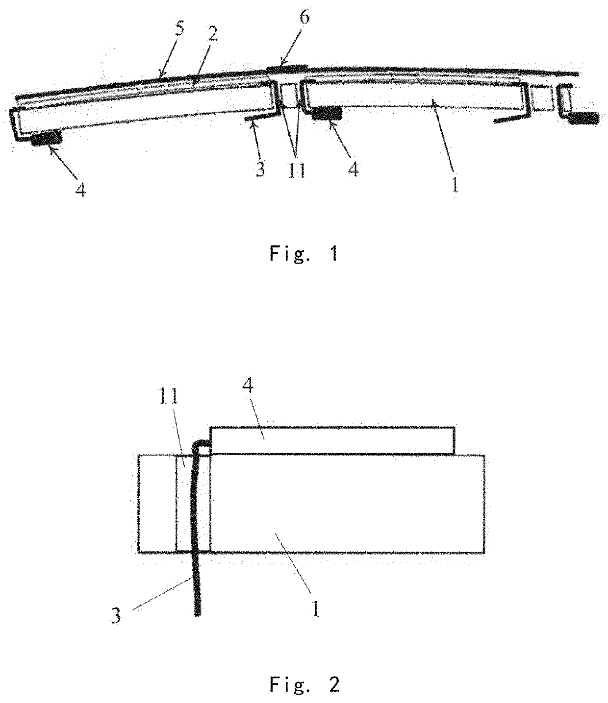
[0040]FIG. 1 is a main cross-sectional view illustrating a roof-mounted solar module integration device provided by an embodiment of the present invention. The embodiment of the present invention provides a roof-mounted solar module integration device comprising a substrate 1, a solar module 2, a plurality of conductive bands 3, a bypass diode 4 and an anti-reversion diode.

[0041]wherein a plurality of substrates 1 are spliced with one another to serve as the...


PUM


Abstract

The present invention provides a roof-mounted solar module integration device, a solar power vehicle and a encapsulation method for modules. The integration device comprises: a substrate in which a through-hole is formed, wherein a front side of the substrate is provided with a first trench, and a reverse side of the substrate is provided with a second trench; a solar module fixed on the front side of the substrate; a plurality of conductive bands arranged in the first trench, wherein a first end of each of the conductive bands is connected with the solar module, and a second end is led out of the through-hole to the reverse side of the substrate; and a bypass diode and an anti-reversion diode which are arranged in the second trench and connected with the second ends of the conductive bands. According to the roof-mounted solar module integration device, the solar power vehicle and the encapsulation method for modules as provided by the present invention, the trenches and the through-hole are formed in the substrate to achieve the arrangement of the bypass diode, the anti-reversion diode and the conductive bands, which solves the problem in the prior art that electrical wiring control is not accurate, thereby increasing the amount of incident light of the solar module, simplifying the process, and improving the accuracy of electrical arrangement.

Description

CROSS-REFERENCE TO RELATED APPLICATION[0001]This application is a national phase entry under International Application No. PCT / CN2017 / 101482 filed on Sep. 13, 2017, the entire contents of which are incorporated herein by reference.TECHNICAL FIELD[0002]The present invention relates to the technology of solar cells, and more particularly, to a roof-mounted solar module integration device, a solar power vehicle and a encapsulation method for modules.BACKGROUND[0003]As an important constituent part of the solar power vehicle, the solar module is used for converting light energy into electric energy, thereby providing power for the vehicle. To be prevented from being damaged, the solar module in the prior art is subjected to encapsulation.[0004]Currently, in most solar module encapsulation, protective materials (e.g., glass, organic glass, PC or plastic films) are spread and covered on the solar module surface in the manner of lamination However, such a encapsulation manner has the follo...

Claims


Application Information

Patent Timeline
IPC IPC(8): H01L31/046H01L31/0443H01L31/048H02S20/30H01L31/18B60L8/00B32B3/12B32B3/26
CPCB32B2457/12H01L31/0481B32B3/12H01L31/046B32B3/266B60L8/003B32B2262/101H01L31/0443H02S20/30H01L31/18H01L31/0504H01L31/188H01L31/044Y02B10/10Y02E10/50Y02T10/7072B60K16/00B60K2016/003H01L31/0203H01L31/0445
Inventor MING, QIAOHONGGAO, WEIMINXU, KANGCONGXIAO, HANSONGYAN, TINGGUO, GUANGXIYU, XIANGZHOU, WEI
Owner DONG HAN NEW ENERGY VEHICLE TECH CO LTD
Why Eureka
Try Eureka