Refrigeration apparatus with shutoff valve

Active Publication Date: 2019-12-05
DAIKIN IND LTD
View PDF2 Cites 4 Cited by
  • Summary
  • Abstract
  • Description
  • Claims
  • Application Information

AI Technical Summary

Benefits of technology

The present invention relates to a refrigeration apparatus and a method for its operation. The technical effects include preventing breakage of the refrigeration apparatus due to increased pressure of the refrigerant, shutting off the failed portion to release the enclosed refrigerant efficiently, downsizing the utilization unit, and achieving efficient use of space. Additionally, the invention eliminates the necessity of providing a dedicated pressure sensor.

Problems solved by technology

Some substances used as the refrigerant are toxic to humans or cause suffocation.

Method used


Image

  • Refrigeration apparatus with shutoff valve
  • Refrigeration apparatus with shutoff valve
  • Refrigeration apparatus with shutoff valve

Examples


first embodiment

(1) General Configuration

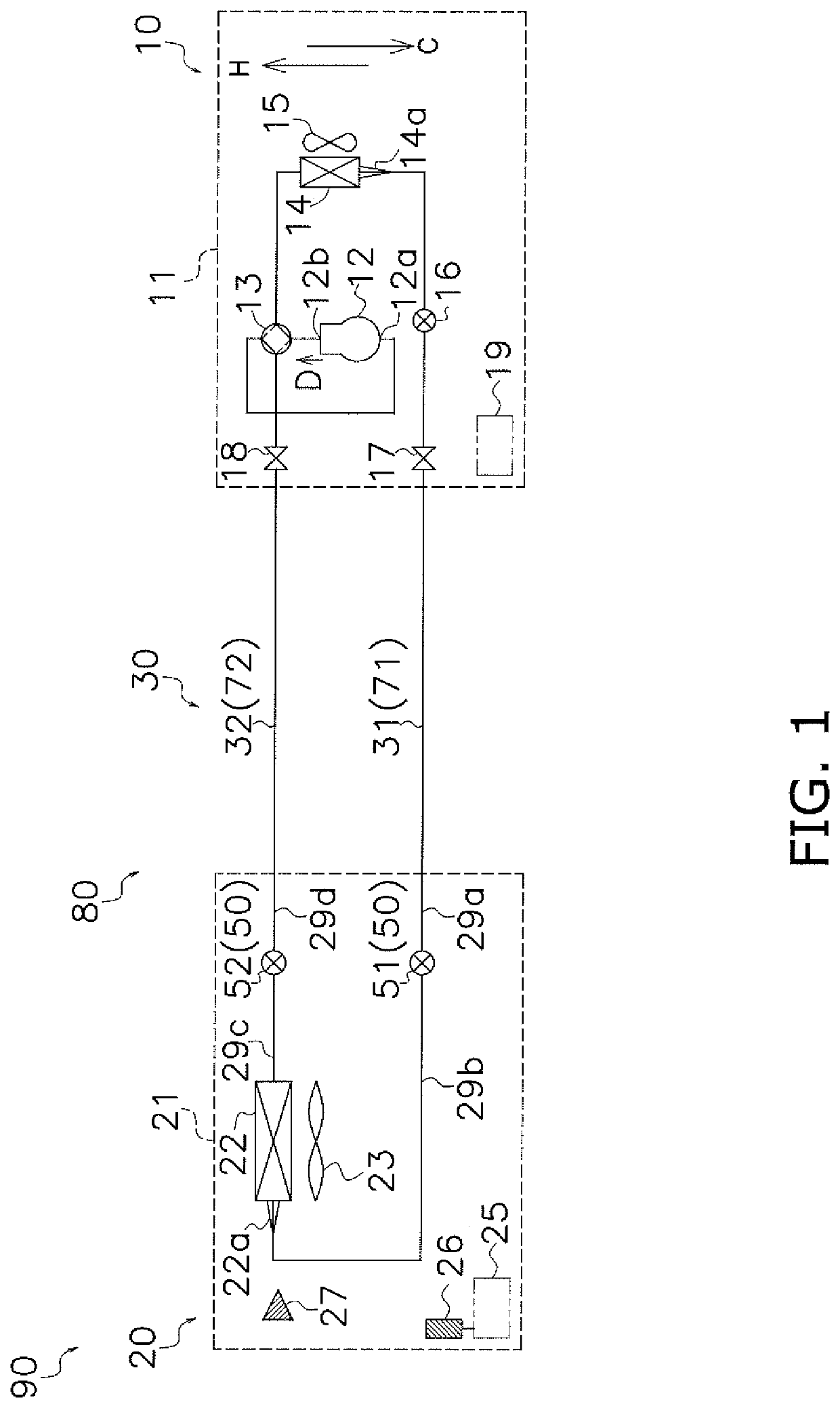
[0029]FIG. 1 shows a refrigeration apparatus 90 according to a first embodiment of the present invention. The refrigeration apparatus 90 is configured as an air conditioning apparatus. Alternatively, the refrigeration apparatus 90 may be implemented as other apparatus such as a refrigerator or a hot water supplier. The refrigeration apparatus 90 includes a refrigerant circuit 80 which carries out a refrigeration cycle through circulation of a refrigerant. The refrigerant circuit 80 includes a heat source unit 10, a utilization unit 20, and a connection pipe 30.

(2) Configuration Details

(2-1) Heat Source Unit 10

[0030]The heat source unit 10 functions as a cold source or a hot source, and is representatively installed outdoors. The heat source unit 10 includes a casing 11, a compressor 12, a four-way switching valve 13, a heat-source-side heat exchanger 14, a fan 15, a heat-source-side expansion valve 16, a liquid-side stop valve 17, a gas-side stop valve 18, a...

second embodiment

(1) Configuration

[0088]FIG. 6 shows a refrigeration apparatus 90A according to a second embodiment of the present invention. The refrigeration apparatus 90A is different from the variation 1D according to the first embodiment in including a plurality of utilization units 20. The refrigerant circuit 80 includes a plurality of utilization units 20, a valve unit 40A, and a heat source unit which is not shown and connected to the valve unit 40A.

[0089]Each of the utilization units 20 includes a first shutoff valve 51. The first shutoff valve 51 not only shuts off the refrigerant circuit 80 upon detection of a refrigerant leakage, but serves also in decompressing the refrigerant.

[0090]The valve unit 40A includes the casing 41, the controller 45, the refrigerant leakage detector 46, the refrigerant pressure acquiring part 47, and a switching mechanism 49. The controller 45 further communicates with the controller 19 of the heat source unit 10 and the controller 25 of each utilization unit ...


PUM


Abstract

A refrigeration apparatus includes a refrigerant circuit including a utilization unit. The utilization unit includes: a heat exchanger; a first refrigerant pipe and a second refrigerant pipe connected to the heat exchanger; and a first shutoff valve and a second shutoff valve whose opening degrees are adjustable and which are respectively provided at the first refrigerant pipe and the second refrigerant pipe. The refrigeration apparatus includes: a refrigerant leakage detector; a refrigerant pressure acquiring part; and a controller configured to adjust the opening degrees of the first shutoff valve and the second shutoff valve. In an alert state where the first shutoff valve and the second shutoff valve are both closed and the refrigerant leakage detector detects the leakage, the controller adjusts the opening degree of at least one of the first shutoff valve and the second shutoff valve to open when the pressure of the refrigerant is greater than a predetermined threshold value.

Description

TECHNICAL FIELD[0001]The present invention relates to a refrigeration apparatus with a shutoff valve.BACKGROUND ART[0002]A refrigerant circulates through a refrigerant circuit which is a component of a refrigeration apparatus such as an air conditioner, a refrigerator, or a hot water supplier. Some substances used as the refrigerant are toxic to humans or cause suffocation. In order to minimize any detrimental effect on the user's health by the refrigerant leaked out from the refrigerant circuit, what may be installed is a circuit shutoff mechanism configured to shut off part of the refrigerant circuit including the portion where the leakage has occurred. For example, Patent Literature 1 (Japanese Patent No. 5517789) discloses an air conditioner including a circuit shutoff mechanism which includes an expansion valve and an electromagnetic valve.SUMMARY OF THE INVENTIONTechnical Problem[0003]In a pipe shut off by the circuit shutoff mechanism, a certain amount of refrigerant is enclo...

Claims


Application Information

Patent Timeline
IPC IPC(8): F24F1/32F24F11/88
CPCF24F11/84F24F1/32F25B49/02F24F11/89F25B1/00F24F11/88F25B49/005F25B13/00F25B2500/222F25B2500/07F25B2600/2525F25B2313/0314F25B2700/2104F24F11/36F25B41/22
Inventor SHIOHAMA, KOUSUKENOUCHI, YOSHITERU
Owner DAIKIN IND LTD
Why Eureka
Try Eureka