
Condensation particle counter efficiency compensation for altitude

a technology of efficiency compensation and condensation particle, applied in the direction of instruments, nanoparticle analysis, suspensions, etc., can solve the problems of high uncertainties in cpc count, complex instrumentation, and easy failure of condensation particle counters, etc., to achieve the effect of improving the efficiency of measurement system and avoiding failure of other good measurement systems

Active Publication Date: 2019-12-05
TSI INC
View PDF0 Cites 2 Cited by
  • Summary
  • Abstract
  • Description
  • Claims
  • Application Information

AI Technical Summary

Benefits of technology

The patent text describes a method for improving the accuracy of measurements made by a condensation particle counter (CPC) in high-altitude environments. The method compensates for changes in particle count, caused by changes in sampled absolute-pressure, by using a calibration technique that ensures minimal measurement uncertainties. The CPC is a device that detects particles by condensing vapor onto them, and the method compensates for changes in particle count by controlling the degree of supersaturation of the vapor. This allows the CPC to be used at various values of absolute pressure with minimal measurement uncertainties, which is important for regulatory applications. The technical effect of this patent is to improve the accuracy of CPC measurements in high-altitude environments.

Problems solved by technology

The science of condensation particle counters, and the complexity of the instrumentation, lies with the technique to condense vapor onto the particles.
High uncertainties in CPC count could easily fail an otherwise good measurement system.
The error can have a significant effect on, for example, whether an engine or engine system can pass a certification test or not.
A discrepancy may occur due to the particle losses to the walls, non-uniform temperature and flow profiles, and insufficient residence time in the actual CPC.
Some uncertainties of the modeling parameters such as mass, thermal mass diffusivities, and a boundary layer effect may also contribute to the discrepancy.
This large counting error is not acceptable for a high precision instrument such as a CPC and the error can easily fail, for example, regulatory applications that have more stringent pass / fail criteria.

Method used


Image

  • Condensation particle counter efficiency compensation for altitude
  • Condensation particle counter efficiency compensation for altitude
  • Condensation particle counter efficiency compensation for altitude

Examples


Embodiment Construction

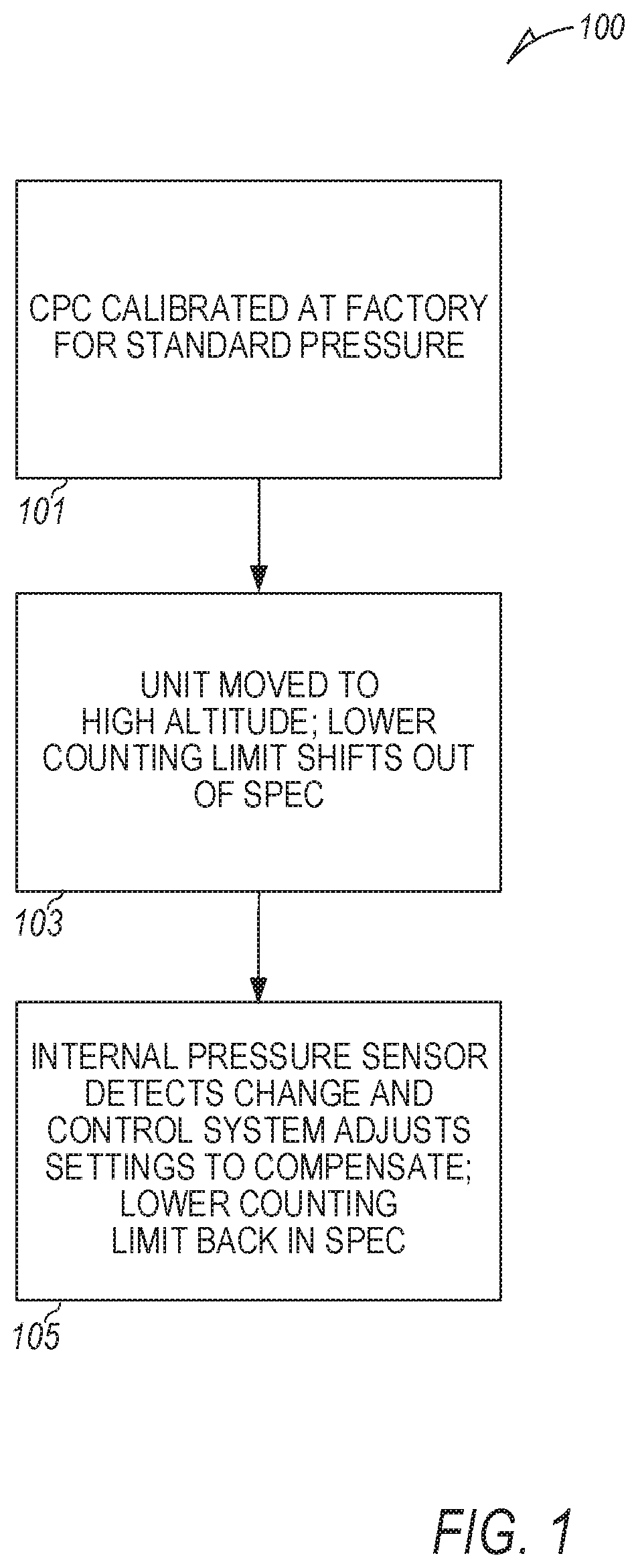
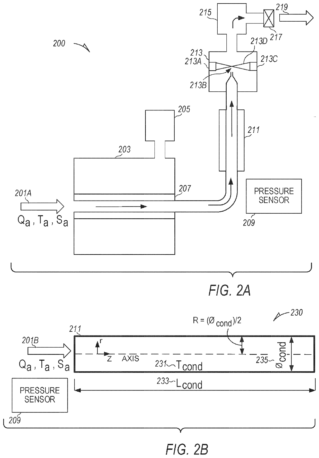
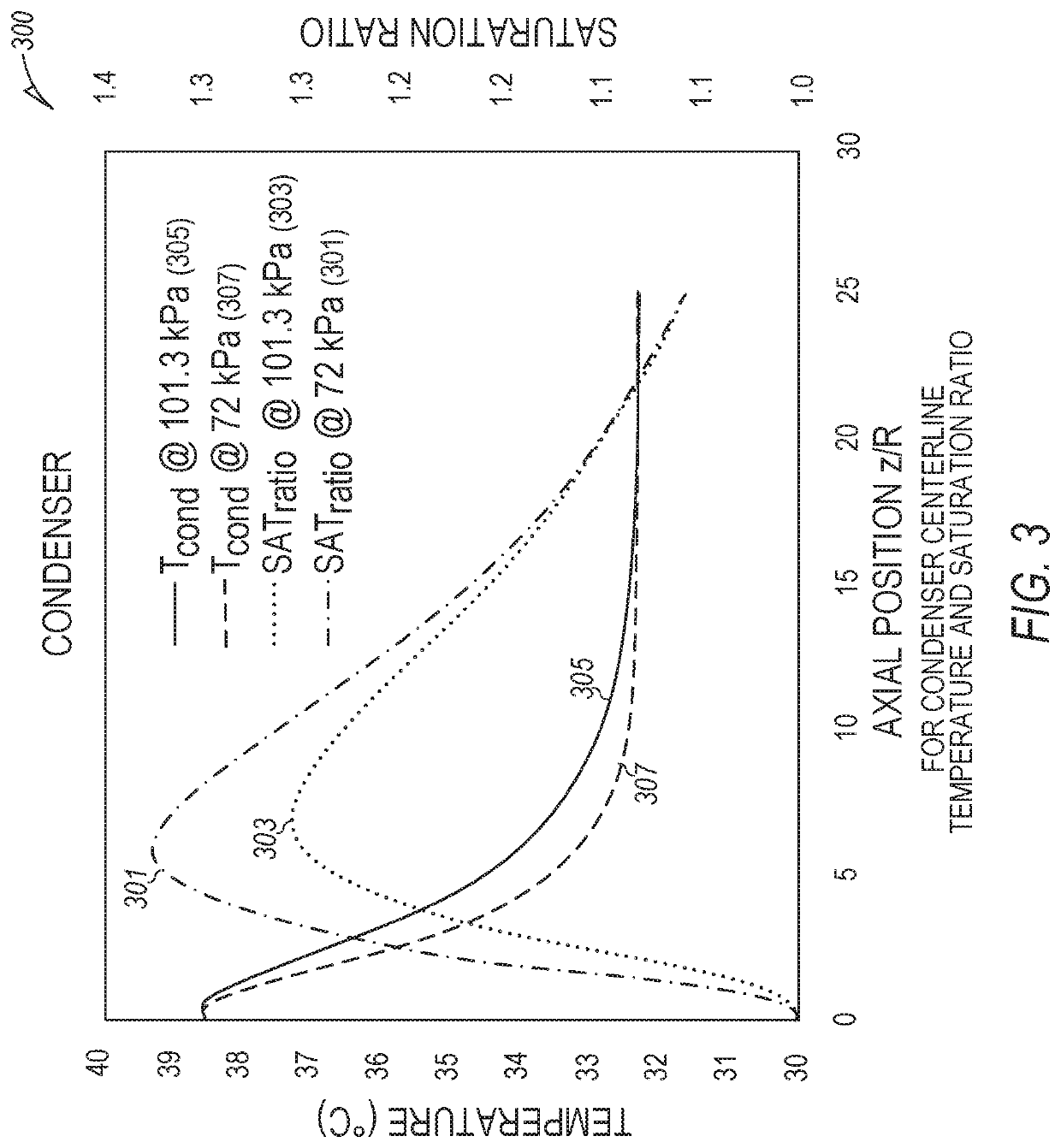
[0014]The science of condensation particle counters, and the complexity of the instrumentation, lies with the technique to condense vapor onto the particles. When the vapor surrounding the particles reaches a specific degree of supersaturation, the vapor begins to condense on the particles. The magnitude of supersaturation determines the minimum detectable particle size of the CPC. Generally, the supersaturation profile within the instrument is tightly controlled. Techniques and mechanisms are disclosed to compensate for changes in particle count, at a given particle diameter, for changes in sampled absolute-pressure (e.g., a value of absolute pressure of an aerosol stream through the CPC) at which the measurements are taken.

[0015]Since a CPC is normally factory-calibrated at a certain pressure (typically at an absolute pressure of 101.3 kPa), techniques and mechanisms disclosed here allow a CPC to be used at various values of absolute pressure with minimal measurement uncertainties...


PUM


Abstract

The disclosed subject matter compensates or corrects for errors that otherwise would be present when a measurement is made on a condensation particle counting system with the only difference causing the errors being absolute pressure. The difference in absolute pressure may be due to, for example, a change in altitude in which the condensation particle counting system is located. Techniques and mechanisms are disclosed to compensate for changes in particle count, at a given particle diameter, for changes in sampled absolute pressure at which measurements are taken. Other methods and apparatuses are disclosed.

Description

CLAIM OF PRIORITY[0001]This application claims the benefit of priority to U.S. Provisional Patent Application Ser. No. 62 / 677,622, filed on 29 May 2018, and entitled, “CONDENSATION PARTICLE COUNTER DETECTION EFFICIENCY COMPENSATION FOR ALTITUDE,” which is incorporated by reference herein in its entirety.BACKGROUND[0002]In a number of airborne particle measurement studies, a condensation particle counter (CPC, also known as a condensation nucleus counter, CNC) is used to detect particles in a monitored environment; the particles being too small to scatter enough light to be detected by conventional detection techniques (e.g., light scattering of a laser beam in an optical particle counter). The small particles are grown to a larger size by condensation, from a working fluid within the CPC, being formed on the particle. That is, each particle serves as a nucleation seed for the working fluid; a vapor, which is condensed onto the particles to make the particles larger. After achieving ...

Claims


Application Information

Patent Timeline
IPC IPC(8): G01N15/08G01N15/06
CPCG01N2015/1486G01N15/0826G01N15/065G01N2015/0042G01N2015/0038G01N2015/0046
Inventor CALDOW, ROBERTJOHNSON, JASON PAULHAN, HEE-SIEWSCHECKMAN, JACOB
Owner TSI INC
Learn More